This thread has been locked.

If you have a related question, please click the "Ask a related question" button in the top right corner. The newly created question will be automatically linked to this question.

TPS659039-Q1: About the contents of the TPS659039 register

Part Number: TPS659039-Q1

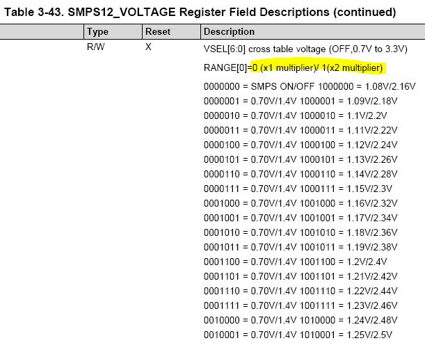
We want to read the SMPS channel output voltage value of the PMIC, but we don't understand the contents of the VSEL value in the VOLTAGE Register of the Register Map.

Question 1: In the screenshot below, does the content marked in yellow mean the range value?

Question 2: Why are there many groups of VSELs equal to 0.70V/1.4V? We think that such voltage values seem to be meaningless for monitoring.

  • Hi Feng,

    The SMPS12_VOLTAGE register is one of the two ways used for setting the voltage, not monitoring it. The other is the SMPS12_FORCE bits. 0b0000001 through 0b0010001 all correspond to the minimum output voltage level option and they are duplicated because there are more bits combinations available than actual output voltage settings.

    The RANGE bit determines if the voltage chosen is the 0.7V to 1.65V or 1.0 to 3.3V range. This is explained in the register map www.ti.com/.../swcu119

    If you would like to monitor the voltage, you could use the GPADC for this purpose. There is an app note on its use: www.ti.com/.../slia087
  • Hi Kevin,

    We can select the different GPADC monitor internal channels in the register GPADC_SMPS_ILMONITOR_EN Register, then read the GPADC diagnostic voltage value in the register GPADC_SMPS_VSEL_MONITORING Register, right?

    The screenshot below is the content of the GPADC_SMPS_ILMONITOR_EN Register. It looks like the SMPS8 and SMPS9 channels are invalid, right?

  • Hi Feng,

    GPADC_SMPS_VSEL_MONITORING can be read to see the voltage setting of the chosen buck. It is not a measurement but as long as the PMIC is working properly, it should be within the DC accuracy of the device. You are right that current monitoring of SMPS8 and SMPS9 is not supported.

    If you wanted to measure the actual voltage, GPADC_IN0, GPADC_IN1, or GPADC_IN2 can be used.

    For future questions, our device expert Nastasha will help here.

  • Hi Nastasha,

    Ok, so The six internal channels for self-monitoring which mentioned in the technical documentation, are the yellow labels in the image below, right? In which registers can we read these internal monitoring information?

    By the way, are the voltages in the GPADC_TRIM7 and GPADC_TRIM8 registers coming from the VCC1 pin or the VCC_SENSE pin?

  • Feng,

    See Table 6-3 (GPADC Channel Assignments) to see how to get this information from the GPADC. You can read these internal channels by selecting which GPADC channel you are reading in the GPADC registers.

    The GPADC_TRIMx registers should not be modified. They are not voltages, but rather trim values to improve accuracy of the GPADC.

    Thanks,

    Nastasha