This thread has been locked.

If you have a related question, please click the "Ask a related question" button in the top right corner. The newly created question will be automatically linked to this question.

TPS63020: Boot-up resonate issue?

Genius 5355 points
Part Number: TPS63020
Other Parts Discussed in Thread: TPS3839

Hi Support,

Issue:

  • When input VBAT > 3.7V, the output is okay at 3.8V. Then reduce the VBAT to 3.2V, it’s still working. -> OKAY
  • When input VBAT < 3.6V, let’s say VBAT = 3.4V, the output is about 1.8V -> NOKY

Please advise.

Thanks.

  • Hi Ikon,

    So, the problem only occurs during start-up if VBAT < 3.6 V? Could you please send us the scope plots during start-up (Vin and Vout)?

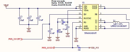
    If startup is the problem, first make sure that the impedance between the power supply and VIN is low. And also make sure that the PCB layout is as close as possible to the one recommended in the datasheet.

    Best regards,
    Milos
  • Hi Milos,

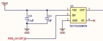
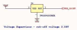
    We found that voltage supervisor TPS3839G33DBZR  doesn’t work when it’s connected to EN pin of LDO TLV70233DBVR & bock-booster TPS63020DSJT. Suspect it’s due to load impendence.

    To correct the design, the question is that what the load impendence of voltage supervisor TPS3839G33DBZR is allowed for voltage supervisor TPS3839G33DBZR?

    Thanks.

  • Hello Ikon,

    Please check if the problem is gone when you remove C9. At startup, C9 is a short to GND and this might draw too much current from the output of the supply voltage supervisor.

    It is as well possible that during startup, the input impedance between VBAT and TPS63020 is high enough that the voltage falls below the 3.08V of the TPS3839G33 and the devices get disabled again.

    If this does not solve your issue, please send scope pictures of VBAT, PWR_ONOFF, and VOUT of TPS63020.
  • Hi Brigitte,

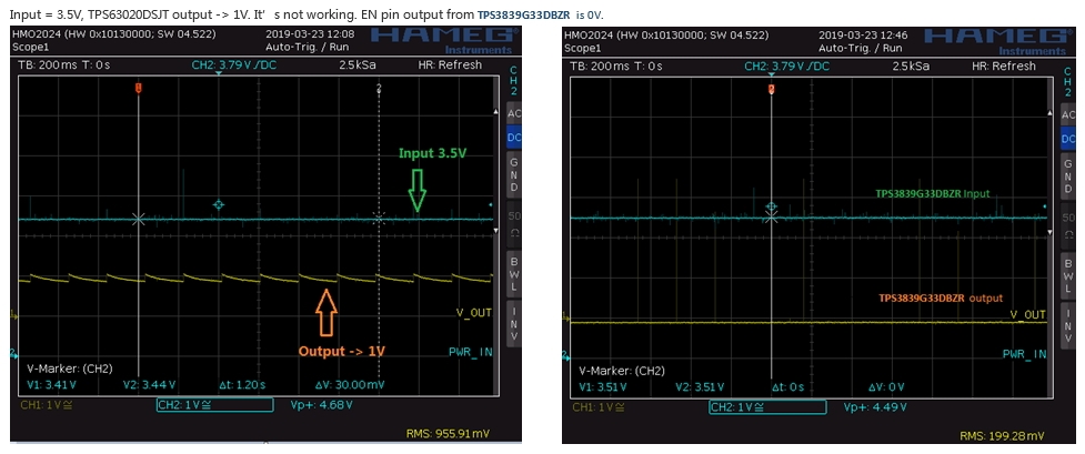
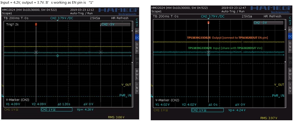
    We removed the 0.1uF capacitor but problem still remains. The waveform is captured below:

    Thanks.

  • Hello Ikon,

    Please have a detailed look at the EN pin in the first case. To me it seems that your scope plot of the EN pin shows that it goes high for very short periods of time, see below. This means that the TPS63020 gets turned on and off which is reflected at the output rising.

    It seems that there is no capacitor added on the VDD of TPS3839G33. Please add such a decoupling capacitor. This might solve the issue.

  • Hi Brigitte,

    We suspect this might not be the root cause.

    The TPS3839G33DBZR input is the power supplier input with big cap. The noise is due to measurement probe but not the source itself. 

    We believe it’s due to TPS3839G33DBZR output impedance impacts the performance.

    Please advise TPS3839G33DBZR output impedance requirement as it’s not shown in datasheet.

    Thanks.

  • Hello Ikon,

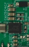
    How long is the distance between the big cap and the TPS3839? It needs a local 0.1uF cap on its power supply.

    Please zoom in on the noise. You are measuring with 200ms/div. This is too long for checking out a signal in detail. As the TPS3839 is turning on at exactly the same points as the TPS3839, I doubt that the spikes are measurement noise.
  • Hi Brigitte,

    #1. Please refer to the picture

    #2. It should not be the case.

    Thanks.

  • Hello Ikon,

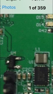
    Where is the TPS3839 on the picture?

  • Hi Brigitte,

    Sorry, took wrong picture. It's U4. Please refer to below.

    Thanks.

  • Hello ikon,

    Would you please measure the voltage on VDD pin of TPS3839 and the RESET voltage on the TPS3839 with 3.4V input with an oscilloscope? Please measure at 10ms/div and on VIN 100mV/div with offset.
  • Hi Brigitte, please see below.

  • Hello Ikon,

    Thank you very much for the measurement. When you did this measurement, the output voltage of the TPS63020 was not correct, right?
    In this measurement PWR_IN is the input voltage on pin VDD and V_OUT is the output voltage on pin /RESET of TPS3839, correct?

    If yes, it would be interesting to repeat this measurement with the trigger set to V_OUT = 2V instead of PWR_IN = 3.4V.
  • Hello Ikon,

    I haven’t heard back so I’m assuming you were able to resolve your issue. If not, just post a reply below (or create a new thread if the thread has locked due to time-out).
  • Hi Brigitte,
    To your queries...
    1. When you did this measurement, the output voltage of theTPS63020 was not correct, right?
    YES.
    2. In this measurement PWR_IN is the input voltage on pin VDD and V_OUT is the output voltage on pin /RESET of TPS3839, correct?
    NO. TPS63020’s EN pin connect to the output voltage on pin /RESET of TPS3839.
    Please advise any where to debug.
    Thanks.
  • Hello Ikon,

    It would be interesting to repeat this measurement with the trigger set to V_OUT = 2V instead of PWR_IN = 3.4V.
  • Hello Ikon,

    I haven’t heard back so I’m assuming you were able to resolve your issue. If not, just post a reply below (or create a new thread if the thread has locked due to time-out).