This thread has been locked.

If you have a related question, please click the "Ask a related question" button in the top right corner. The newly created question will be automatically linked to this question.

LM5021: Doesn't startup properly - Unable to get more than minimum ON time for the MOS

Part Number: LM5021

Hello,

This is my first time designing an isolated power supply. I have the following specifications :

Vin : 38 to 57V

Vout : 24V 30W

Here is my schematic and captures of a few signals.

When no load on output (or a few mA), it goes to 24V. But when I put a load, even 100mA, it doesn't start and keep rebooting.

I've tried to simplify the design by strapping (R63, C119), remove (R61, C102, D5) and put 5k at R62 to force Vin (using internal zener for regulation), CSS tested with 10nF (current captures), 100nF, 1uF. Doesn't change a thing !

The LM5021 is working fine. But I really don't understand how it could do more than 100ns MOS ON time... It's obviously a BIG short circuit when the MOS is turned on...

Could you please help me to understand what's going on ?

Thank you for your time !

Michaël

MOS Gate

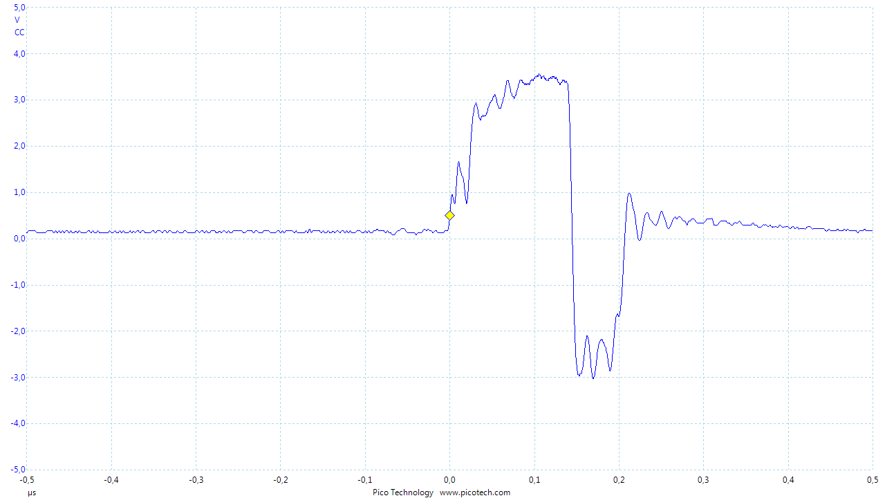
R86 voltage : Obviously it goes well over 0.5V and explains why the LM5021 stops the MOS conduction. Problem is, I really don't understand how it could be different...
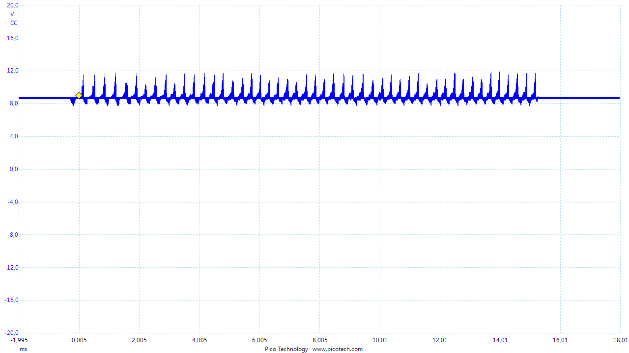
COMP pin

And Vout. We can see that output voltage is rising fast, when the hiccup stops the process.

  • D5 cannot be removed as it is needed to bias the U14.

    Please provide the transformer specs, such as primary inductance, turns ratios, etc.

    Is R86 value 0.15-ohm?

    Please provide U14 VCC waveform together with other waveforms such as MOSFET gate, and CS pin

  • Hello Hong Huang,

    Yes R86 is 150mohms. I've tested with values around 100mohms to 500mohms. Currently it's 125mohms.

    Here is the link to the transformer : https://cdn.sos.sk/productdata/9c/40/329447df/7491195112.pdf

    I know D5 is needed but I've removed it to simplify the design and finding the issue.

    I've changed CSS for 100nF and VOUT=24V with no load.

    When I connect a 50ohms load, here is what appens (Vout waveform and VCC waveform).

    Vout : We can see that the output voltage can't rise to 24V. The MOSFET turn on time is about 100ns at 267kHz so that's not a surprise.

    VCC pin waveform during PWM mode.

  • Please provide CS pin waveform.
  • Please also provide waveform of R86.
  • Please provide the values of R87, C126, and C121.
  • Hello Hong,

    Sorry I didn't manage to make the captures you requested, I've accidentally touched two pins with the oscilloscope and boom !

    I'll repair the board and do the captures.

    Anyway, I was looking at the Rsense waveform and I think there is something really wrong here :

    If you take the 41uH (@ 100kHz) of the transformer primary inductance, take the DC impedance of (transformer's primary, MOS and Rsense - around 200mohms) and trace the transient waveform for 48V -> 2.3A after 2us. On my waveform, it goes crazy high in less than 0.03us. It's like I got a short circuit instead of the transformer's primary.

    There is something wrong here don't you think ?

    Best regards,

    Michaël

  • Yes, there is something wrong if you see that narrow pulses. There are several possibilities.

    One is to confirm if the transformer primary inductance is 41uH - a simple way is to remove the transformer from your board and use an inductance measuring meter to measure.

    Another is to confirm all transformer polarities are correct by testing its polarities so to verify its all physical connections of polarities are correct.

  • any updates?
  • Hello Hong,

    Thanks for asking !

    I bought an LCR meter and received it yesterday.

    Measurements on the transformer (not mounted on the board) @ 100kHz :

    Primary : 41uH (as specified in the datasheet)

    Secondary : 6.3uH each

    So pinout and caracteristics seems OK. I'm thinking layout is not good, I'll start redesining the board and submit schematic and PCB to you. Do you have other ideas ?

    Best regards,

    Michaël

  • I would like to measure three waveforms, MOSFET T2,  Vgs, Vds, and the transformer secondary winding output (transformer pin 6 to pin 10). These waveforms can show if there is polarity issue by real test.

    But if you are sure the transformer polarities correct, then you can skip these.

    Yes, you can send the sch and layout for me to have a look.

  • Please open a new thread when you testing your new board for support. I am closing this thread.