This thread has been locked.

If you have a related question, please click the "Ask a related question" button in the top right corner. The newly created question will be automatically linked to this question.

TPS92075: very low light

Part Number: TPS92075


Hello,

I just powered on my new 230Vac board that uses TPS92075.

This is schematic:


On output there are 4 LED (series, 3Vx4 = 12V), Rsense is 0.95ohm to reach ~500mA

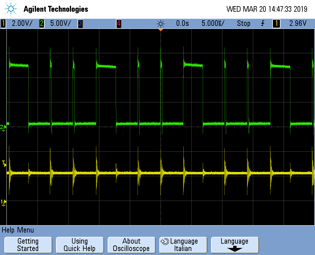
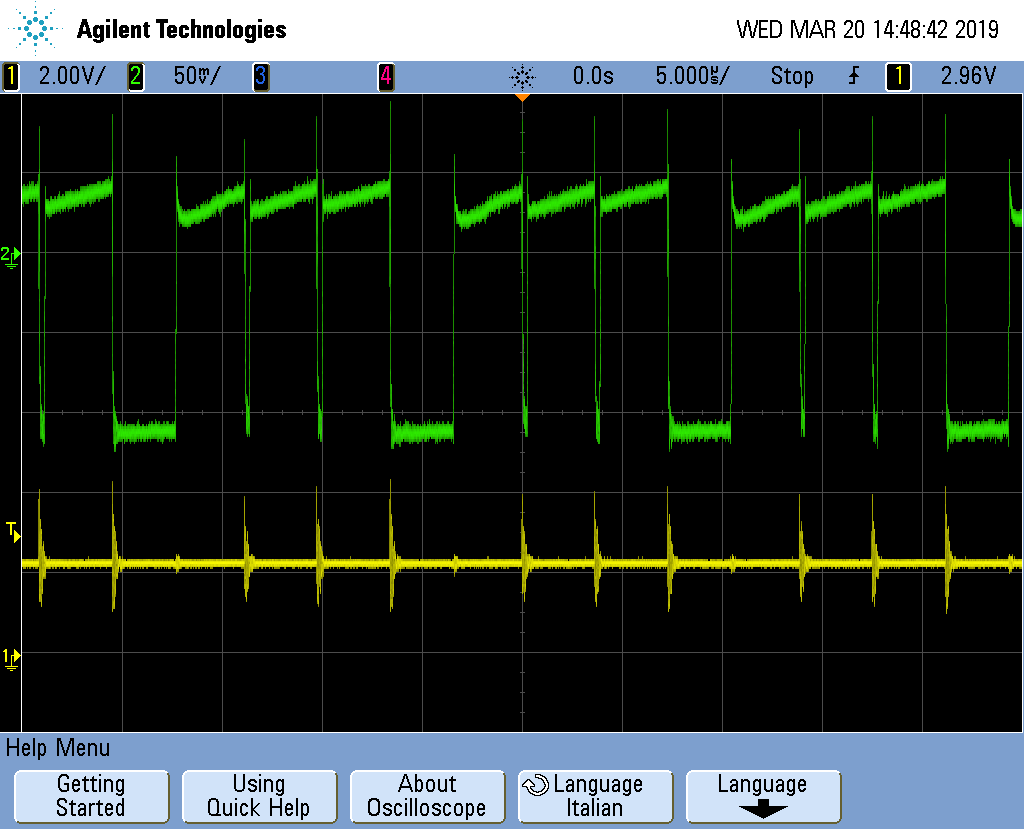
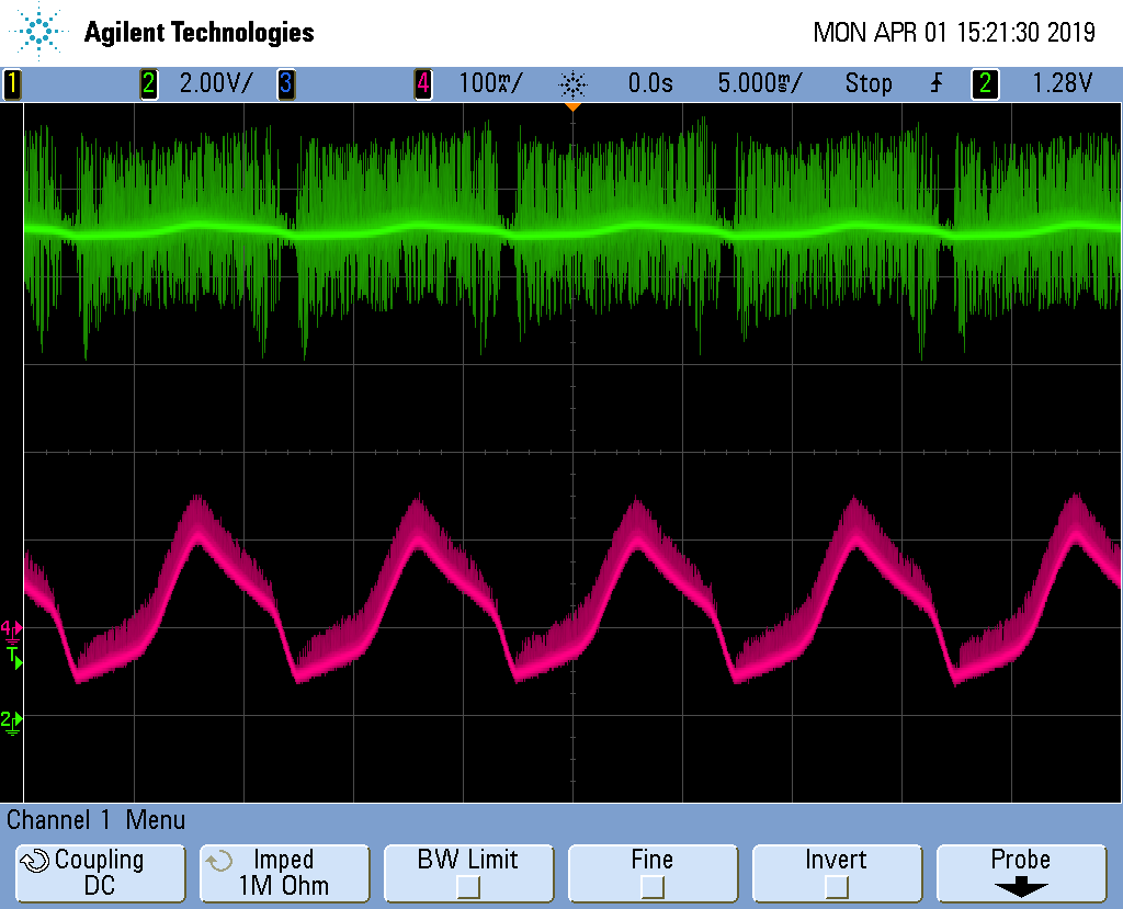
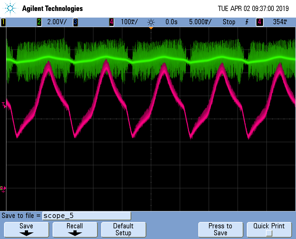
Main problem is that LED current is ~3mA (Voltage on Rsense is ~4mV)

Minor issue is that LED are turning on after 2-3 seconds


What can I check?

I don't need to dimmer it, there are some component that are controlling triac dimmer? Can I remove them?

Thank you a lot

  • Hello ,

    For no triac dimmer you can short R1, remove C2 and R2. Possibly remove R5, D3 and C6.

    What is the voltage on Pin 3 of the TPS92075? or the left side of R8? You can remove R5 to see if the current regulation increases.

    Where did you get the values on your schematic, such as R7, R6, R5, C6, D3?

    If the current is low the turn-on will be slow due to charging C4, so if the current issue gets resolved that may also.

    Best Regards,
  • Hello,

    on pin 3 voltage is ~4mV (0V on R8).

    I removed R5 but nothing is changing.

    At this moment I haven't L1 (I have bought it but it's not arrived yet). I think it's only a filter, does this should be a problem?

    I have also to change D5 with FM4005. At the moment I'm using generic diode that I have at warehouse...

  • Hello,

    If L1 is not in the circuit is is shorted out/bypassed? If it is removed there will be no power to the circuit.

    You cannot use the FM4005, it is not intended to be used at high frequency, it is a 60 Hz rectifier diode. This could false trip the current sense since the diode recovery is so long. D5 needs to be an ultrafast recovery or silicon carbide diode. Look at the datasheet and EVM for examples. 230 VAC is more difficult since even the fast/ultrafast recovery diodes may not be good enough depending on your switching frequency and current.

    Best Regards,
  • Thank you Irwin,

    L1 is shorted.

    I tryed FM4005 and MBR40250 (2 MBR in series) but result is the same.
    I will try with ultrafast diodes to see if this solve the problem.

    best regards
  • Hello,

    Can you look at Pins 1,3, 4, 5 and 6 with an oscilloscope?

    Best Regards,
  • Hello,

    I replaced D5 with BA159

    I tryed using an isolation trasformer 1:1 but board burns just after power up... I don't

    I found blown fuse, R1, R10, R11 and shorted Q1, Q2, D3.

    I powered up a new board using 50Vdc (Does it have sense?)

    It seem's not working well, I don't know if it's not working well because of low input voltage.

    You can see DSO captures here:

    Pin 1 and 3:

    Pin 1-4:

    Pin 1-5:

    Pin 1-6:

    I found L2 and D5 wery hot..

  • Hello,

    I imagine D5 was very hot.  You cannot use a standard recovery diode for a switching power supply.  You need to use an ultrafast or silicon carbide for your voltage.  From a previous post:  "You cannot use the FM4005, it is not intended to be used at high frequency, it is a 60 Hz rectifier diode. This could false trip the current sense since the diode recovery is so long. D5 needs to be an ultrafast recovery or silicon carbide diode. Look at the datasheet and EVM for examples. 230 VAC is more difficult since even the fast/ultrafast recovery diodes may not be good enough depending on your switching frequency and current." BA159 is also a standard recovery (slow recovery) diode.  It will look like a short to a switching power supply and get very hot due to the high frequency repeated recovery.  It is meant for 50/60 Hz rectification.

    I checked your inductor, it starts saturating below your output current requirement, this will also not work and most likely will cause catastrophic failure.  The part states 0.35A for saturation current.  Your waveforms don't make sense, there is offset in them, for example Pin 1 and Pin 6, Pin 6 is the off-time, it trips at 1.2V but that's not what the oscilloscope picture shows.  Also Pin 5 is supposed to be VCC?  If you want to use this inductor for now I would recommend lowering the output current to 0.25A maximum to get it working.

    Best Regards,

    Best Regards,

  • Thank you Irwin,

    I'm using BA159 because in its datasheet I found "Fast Switching" and "For use in fast switching rectification of power supply, inverters, converters and freewheeling diodes for consumer and telecommunication" but I'm waiting ultrafast diodes I bought.

    datasheet BA159

    There is 0.7V offset becaude GND of DSO is before bridge rectifier, so all images have 0,7V offset (in last test I use 50Vdc).

    Probably I have to reduce R4 value to use it with 50Vdc...

    On first schematic I forgot to update L2, sorry. On the boards I have wurth 7447709681: 680uH, saturation current 1,3A. But I will use HV version: 7687709681

    I will try with other diodes and I will tell you how it is working

    Best regards

  • Hello,

    The diode is a very critical part of this design since it is 230 VAC and hard switched.  If you can order a silicon carbide to try it would be a way to eliminate that as an issue.  BA159 recovery is way too slow.  Look at trr, it should be around 35 ns and even then it will be diode dependent to work correct.  The ultrafast recovery diodes should work and to know if the recovery isn't causing issues is by part temperature (the MOSFET and diode).  Silicon Carbide works but is expensive and has a high Vf.  R4 should be okay at lower voltage.  There isn't really anything pulling down on that node except the leakage of the zener.

    Best Regards,

  • Hello,

    I haven’t heard back from you, I’m assuming you were able to resolve your issue.
    If not, just post a reply below (or create a new thread if the thread has locked due to time-out)

    Best Regards,
  • Hi Irwin,

    Not solved yet, I haven't tryed nothing else at the moment....

    I will try with STPSC406D and STTH2R06 diodes, I will update you in few days.

    Best regards

  • Hello Irwin,

    I have some update, I replaced switching diode with SSTH2R06A and incremented values of R4, R6, R7, C7 using values of "designcalculator" spreadsheet  and PMP6016 evaluation board.

    Here is updated schematic:

    Its behaviour is better but I think it's not working well: using smartphone, I can see flicker on output and T2 (switching mos: IPN80R3K3P7) becomes hot.

    I attach here DSO acquisitions to have your opinion.

    PIN1:

    PIN 1 yellow, PIN 3 green:

    Pin 1 yellow, Pin 4 green:

    Pin 1 yellow, Pin 5 green:

    Pin 1 yellow, Pin 6 green:

    Thank you

  • Hello,

    A few things. I would try reducing R9, that value will add to switching loss though the diode has to be able to recover otherwise switching loss can increase (this is choosing the correct freewheel diode). Can you get an oscilloscope picture of the drain waveform near the peak of the rectified AC (this is high voltage)? ST has some that can work though they are not easy to figure out. Your switching frequency seems high for this type of design. I would try to be 100 KHz or lower. A few reasons for this, one is the leading edge blanking but the bigger issue is switching loss and other negative effects. Is it possible to have a higher LED stack voltage at lower current. This design is hurting you because of the step-down ratio making the switching loss much worse due to higher LED current. At 50V the LED current would drop to 125 mA or so.

    I don't understand the CS pin waveform (seems as though it's not consistent), also the circuit added to CS won't work correct at such a low duty cycle as it is. You can see the duty cycle in the last oscilloscope picture, between the two noise spikes is the on-time, the ramp is the off-time, duty cycle is very low (which is expected with 12V output 230 VAC input). At the peak of the AC the duty cycle would be 12V/230V*1.414 = 3.7%. It will be higher due to losses and the freewheel diode but you can see how short the on-time is. Lowering the switching frequency will help the losses a lot but the inductor may need to be a larger value.

    At a 12V output you may also run into problems with VCC. The VCC capacitor may need to increase but it would be better just to have a higher LED stack voltage.

    Best Regards,
  • Hello,

    I increased R3 to 400kohm, reduced R9 to 39R, increased C8 up to 400nF and C4 to 2000uF.

    Frequency now is near 1000kHz.

    Light seems ok, but it has 100Hz flicker.

    Here is waveform of Q1 drain (green) and Q2 drain (yellow) near the peak of the rectified AC:

    Here is LED voltage and current:

    My design must have 12V 500mA output. Do you think that it is difficult or it is impossible?

    What pin do you mean with "CS pin"?

    Thank you and best regards!

  • Hello,

    I assume you mean 100 Khz not 1000 KHz?  It won't work at 1000 KHz.

    100 Hz ripple is going to be there, that is a function of power factor correction.  Also, your current waveform doesn't makes sense, it's going negative.

    Think about the conversion ratio, going from 230 VAC to 12 VDC isn't going to be optimum.  It can work but things like minimum on-time have to be checked.  The MOSFET and diode recovery will see 500 mA, if the output was 48V it would be one quarter of that making switching loss much less.  Also the percentage of loss of the freewheel diode will be higher, Vf/12V versus Vf/48V.  It can work, just not as well as it could.

    CS pin waveform, sometimes there is a slope rise sometimes not and it's not consistent so I don't know what this is:

    Best Regards,

  • Hi Irwin,

    yes, it's near 100khz not 1000kHz...

    Current was coupled in AC, here you can find DC waveform:

    And here you can find PIN 1 (yellow) and PIN 3 (green). There are 2 pictures, one with high values of Vasns and one with low values of Vasns:

    Now CS pin seems to have regular behaviour (with new values as reported on my previous post).

    In the current conditions it seems working, only Q2 becomes hot... but you already told me how to reduce loss on Q2..

    There is a solution to minimize ripple on LED current? I try to add capacitance, it improves but I haven't enough space..

    My target is to use 12V 500mA LED with no ripple on LED current. Is TPS92075 best solution or it's better to use something else?

    Thank you a lot

  • Hello,

    TPS92075 may not be the best choice since the step down ratio is so high but other designs will be more complicated. The 100 Hz ripple is a function of power factor correction from 50 or 60 Hz, increasing the output capacitor value is really the only way to reduce it. What voltage rating are you using for the 1000 uF?

    Best Regards,
  • LED Capacitor is 1000uF 25V

    Thank you for your support, now I have understand better behaviour of TPS92075.

  • Hello,

    If you used a 16V capacitor you could get 2X the value in the same size package. If your output is 12V a 16V capacitor should be fine.

    Best Regards,