This thread has been locked.

If you have a related question, please click the "Ask a related question" button in the top right corner. The newly created question will be automatically linked to this question.

UCC28180: How the IC corrects the power factor without Ac line Sense

Part Number: UCC28180

I am investigating the UCC28180. This IC has no Ac line Sense.

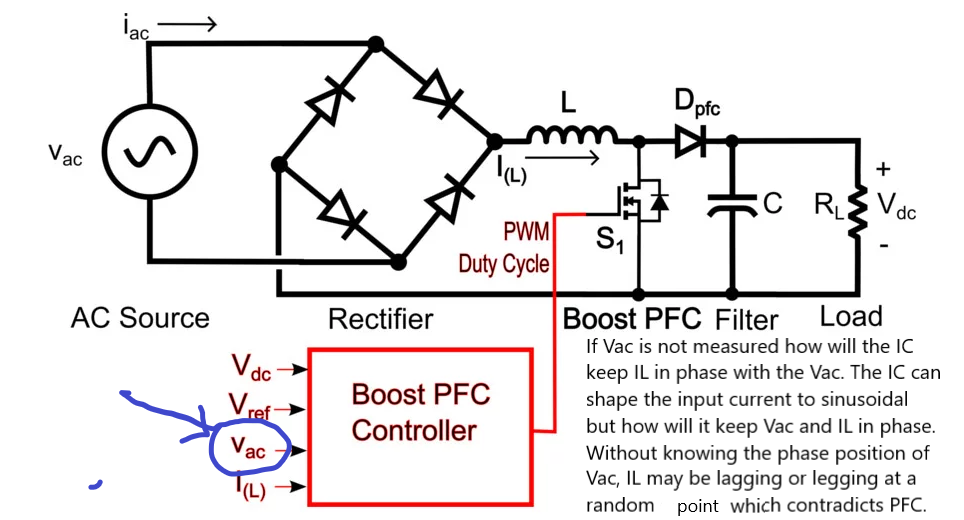
The IC can measure the line current and the PFC Output Voltage (Vsense). The measurement point of Vsense is just after the PFC diode where a smoothening capacitor is placed. This means that at this point the input Ac line phase information is lost. 

If the IC knows nothing abaout the input Ac line Voltage phase position, how will it be possible that the input current is synchronised with the input AC voltage? 

Any app-note describing how the average current mode control of PFC without Ac line sense works is appreciated.  

  • Hello Ferhat,

    Thank you for your interest in UCC28180.
    The IC does not require to look at the AC line voltage, but the controller is sensing the instantaneous current through the PFC boost inductor.
    This is achieved through a sense resistor and a small filter at the ISENSE pin.
    I hope this answers your question.

    Regards,
    Sonal
  • Dear Sonal,

    According to my understanding a PFC controller tries to shape the input current sinusoidal and keep in phase with the input voltage. If the information abaout the phase of the input voltage is missing (not measured by the IC), how can the IC keep the input current in phase with the input AC voltage?

    Best Regards.

  • Hi Ferhat, 

    There is an inner current loop which through the ICOMP pin which senses the input voltage by working out the relationship between input voltage and the duty cycle of the boost topology. 

    If you notice page:13 has the functional block diagram; there is a PWM stage that compares the ICOMP signal with a pre-generated ramp signal and that generates a leading edge modulated signal which is high when the ramp voltage exceeds ICOMP signal. This crossing between the ramp and ICOMP voltage determines the OFF time which resonates to Doff (duty cycle during off period). 

    For a boost topology, Doff=Vin/Vout; here Vin is sinusoidal, and ICOMP being proportional to the inductor current, it follows the current loop forcing the inductor current to follow the input voltage to maintain boost regulation.

    This is explained in further detail under section 8.3.18 in the UCC28180 datasheet.

    I hope this answers your question.

    Regards,

    Sonal

  • Dear Sonal,

    Thank you for the detailed information. I just imagined what happens if the input is an output of a 6 or 12 pulse rectifier (or even a pure DC) where the ripple is much less and the phase angle is very small (30 or 60 degrees.)

    If you have a short answer it would be great. If not it may be the scope of another question.

    Best regards.

    I also investigated the following link which describes the inner loop and the extraction of the hidden Vac from the input current. But I believe this algorithm works only for single phase rectification (B4 rectifier). For 6 pulse or 12 pulse rectifiers the extraction of the hidden Vac will be ineffective as the ripple and phase angle will be much less.

    e2e.ti.com/.../is-pfc-possible-without-input-voltage-sensing

  • Hi Ferhat,

    The short answer is the controller will not care what the input is because even if it is not sensing the voltage directly, this information is inferred from the internal ramp voltage and duty cycle information.

    Regards,
    Sonal
  • Thanks for the detailed information.

    Best regards.