This thread has been locked.

If you have a related question, please click the "Ask a related question" button in the top right corner. The newly created question will be automatically linked to this question.

TPS7A39: Question about TPS7A39 resistor values

Part Number: TPS7A39

Hi,

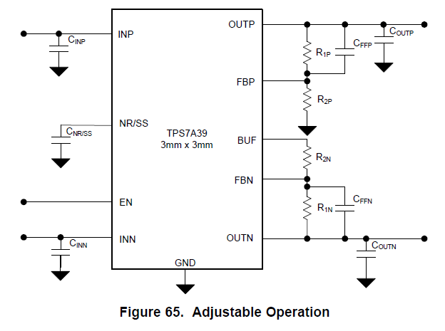
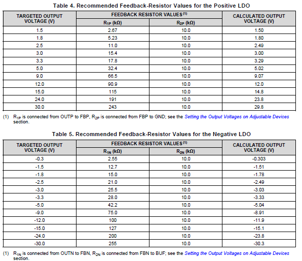
I want to use the TPS7A39 to regulate two 3.7V batteries to +-3.3V. According to the typical application circuit and tables attached (extracted from the device's datasheet), the resistors for this would be R1p = 17.8k, R2p = 10k, and R1n = 28k, R2n = 10k.

My question is, would it be possible to obtain the same 3.3V output with another ratio of resistors? According to the formula, using the suggested values of R1p and R2p, I can obtain the value of VNR/SS, and thus I can get different values of resistors that would, in paper, get the same 3.3V (or very close to it). The same can be done for the negative supply. For example, using R1p = 17.8k, R2p = 10k, and R1n = 28k, R2n = 10k, I got:

3.3 = VNR/SS*(1+17.8/10) => VNR/SS = 1.18. So, trying to adjust to my available SMD resistor values, I got: R1p = 12k and R2p =6.8k, giving a Vout = 3.28V.

-3.3V = VNR/SS*(-28k/10k) => VNR/SS = 1.18 (should've expected that it would be the same). And trying to adjust the values to my resistors, I got R1n 22k = and R2n = 7.8k, giving a Vout = -3.32V.

Is this calculation going to output the desired voltage if connected to the circuit attached? Or do I have to use the specified ones that are on the table?

Thanks in advance,

Roberto

  • Hi Roberto,

    You do not have to use the exact resistor values listed in Table 4 and Table 5 in the datasheet. The ratio between R1 and R2 is what determines the output voltage of the LDO. For comparison, the ratio from Table 4 is 17.8k/10.0k = 1.78, and the ratio from your resistors is 12k/6.8k = 1.76. This results in very similar output voltages. This can be seen from Equation (1) and Equation (2) of the datasheet, which show the output voltages are functions of the voltage reference (VNR/SS) and the feedback resistor ratio (R1P/R2P and R1N/R2N):

    Note that the feedback network must have a minimum current of 5 uA to ensure output accuracy. This requirement sets the upper limit for the feedback resistors. For a 3.3 V output voltage, the sum of the feedback resistors must less than or equal to 3.3 V / 5 uA = 660 kOhms. For this device, there is no minimum feedback resistor requirement, but keep in mind that using smaller feedback resistors will increase power dissipation: Pdiss = Vout^2 / (R1 + R2).

    Thanks,

    Gerard Copeland

  • Excellent! Thank you!