- Ask a related questionWhat is a related question?A related question is a question created from another question. When the related question is created, it will be automatically linked to the original question.
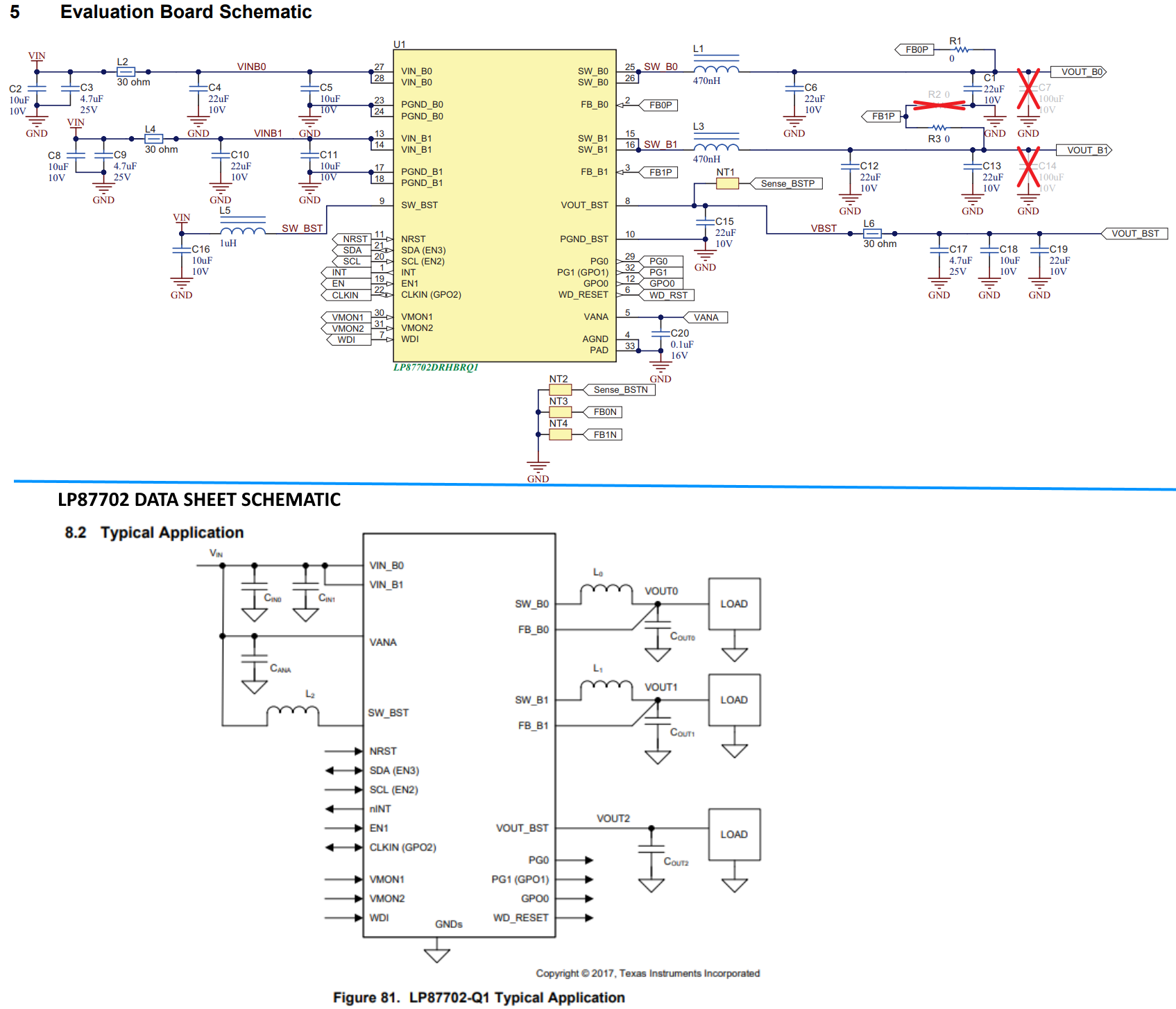
The datasheet for the LP87702-Q1 Evaluation Board Schematic (below) shows two input circuits for VIN_B0 and VIN_B1 even though the input voltage VIN is the same for both.
However, the data sheet for the part shows a single circuit connected to both VIN_B0 and VIN_B1. We would like to use a single circuit to reduce part count,
but we have no idea why the EVM and Data Sheet have conflicting circuits.