This thread has been locked.

If you have a related question, please click the "Ask a related question" button in the top right corner. The newly created question will be automatically linked to this question.

LMR36015-Q1: 400kHz Regulator. Higher overshoots on switching node.

Part Number: LMR36015-Q1
Other Parts Discussed in Thread: LMR36015

Hello,

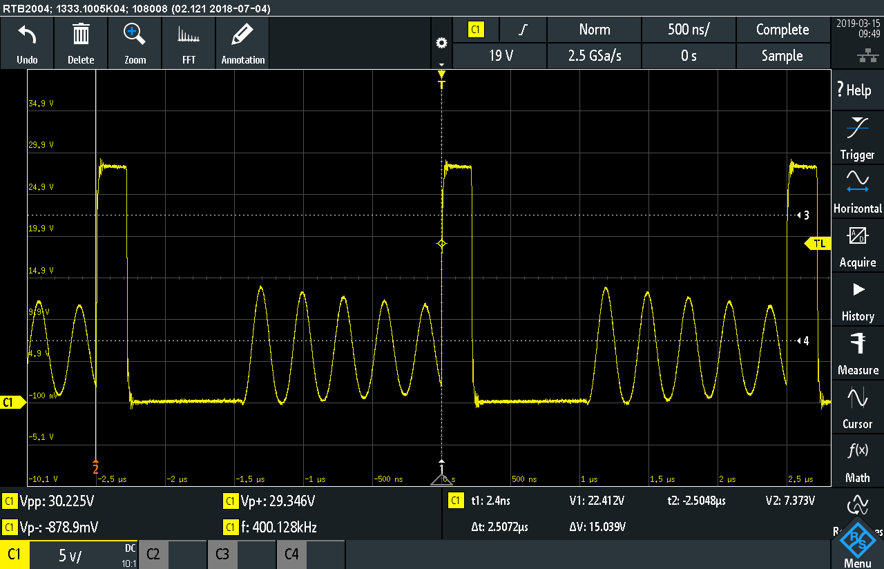
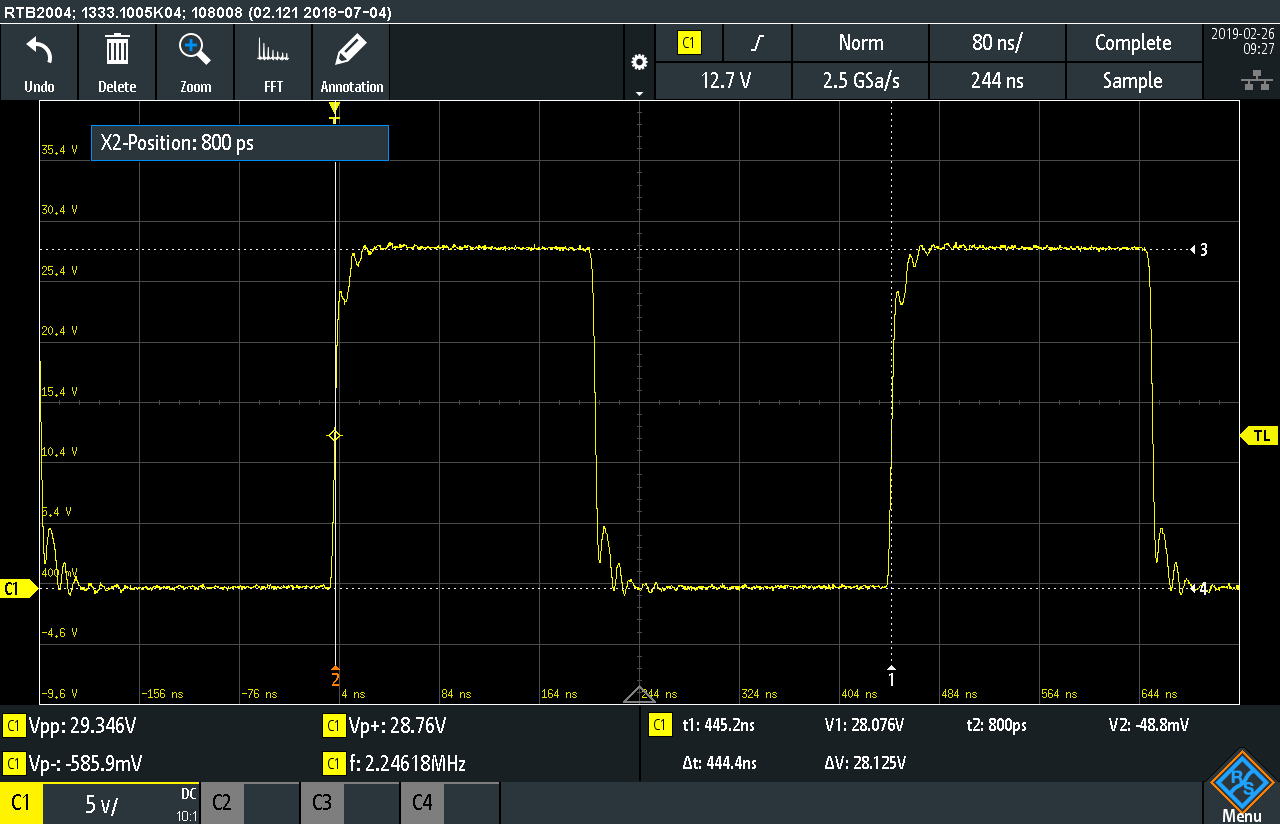
I have a problem with the 400kHz regulator regarding the overshoot on the switching node.

The 2100kHz regulator has better regulation behaviour, but has an other problem, the package goes very hot. See attachments of both measurements.

The increase of input/out capacitance and descrease of coil inductance has no effect of overshoot. 

  • The following parameters are valid to above description: Vin 28,5VDC, Vout 6VDC. Load approx. 100mA.

    -------------------------------------------

    The other circuit measurement below shows much higher overshoot, here is Vin=28,5V, Vout=12VDC. 

    LMR36015, 2100kHz:

    LMR36015, 400kHz:

    Why look this like oscillating circuit? This burst seems to be intended during the regulator idle state (refer to datasheet). Correct?

    But, what is the optimum operating behaviour? To design the circuit for application's nominal loads, so that no burst shall be measured or it doesnt matter?

  • Hello Eugen,

    Both devices ar operating as expected . THe 400Khz switcher is operating in DCM mode and have three unique states duting each switchign period ie High SIde Switch on , low side switch turn on and then the idle state where both switchers are off . When both switchers are turn off , the current in the inductor is zero, and the voltage of the PH node is expected to be equal to the output voltage. In reality, the PH voltage waveform
    oscillates because the output inductor and the junction capacitance of the low side FET constitute a resonant LC network. Hence you see the oscillation .

    ---Ambreesh
  • Hello Ambreesh,

    thank you for clarification!

    With our ECU we have to pass the EMI automotive CISPR25 class 5 tests. So, I have to design low-EMI emission behaviour of the regulators, we have three of them onboard.

    What is the best regulator configuration regarding this idle state - as less as possible of them or does this no matter? I mean if I increase the coil inductance no idle state is measurable even at light loads such as 300-400mA. What is a good practice?

    Regards, Eugen   

  • Eugen ,

    You should be able to meet CISPR EMI standard by adding a small EMI filter at the input . The filter should be able to filter out any high frequency as long as their Self resonance frequency is higher .

    ---Ambreesh
  • Hello Ambreesh,

    Thank you.

    Best regards, Eugen