This thread has been locked.

If you have a related question, please click the "Ask a related question" button in the top right corner. The newly created question will be automatically linked to this question.

BQ25606: When the BQ25606 battery is fully charged, the status indicator is not correct

Part Number: BQ25606

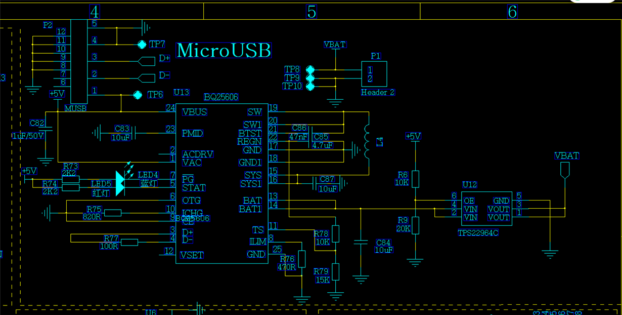
We are using BQ25606 for battery charging management. When the charging is nearly full, sometimes the stat indicator (LED5) flickers, and the battery voltage is 4.12v as measured by a multimeter.Re-plug the charging interface, and you can charge normally again.As shown in the schematic diagram above, what might be the reason?What can I do to avoid this

  • Hi Allen,

    The bottom row of Table 4 below lists all the conditions which can cause the STAT pin to blink:

    Looking at your schematic, input overvoltage shouldn't be an issue because your VBUS = 5 V. TS fault also shouldn't be the problem because you have a fixed resistor divider with no thermistor connected to the TS pin, so your TS voltage is always set to 60% of REGN.

    If possible, can you send a waveform showing VBAT, IBAT, STAT, SW, and VSYS right when the STAT pin starts blinking so we can narrow the issue down further?

    Best regards,

    Angelo

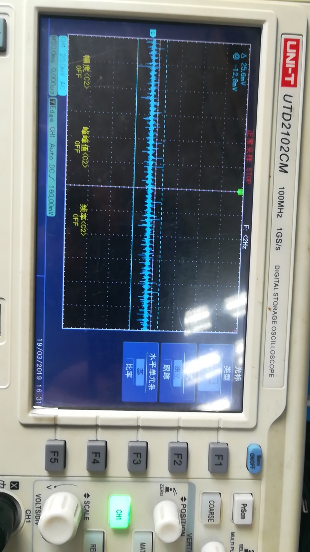
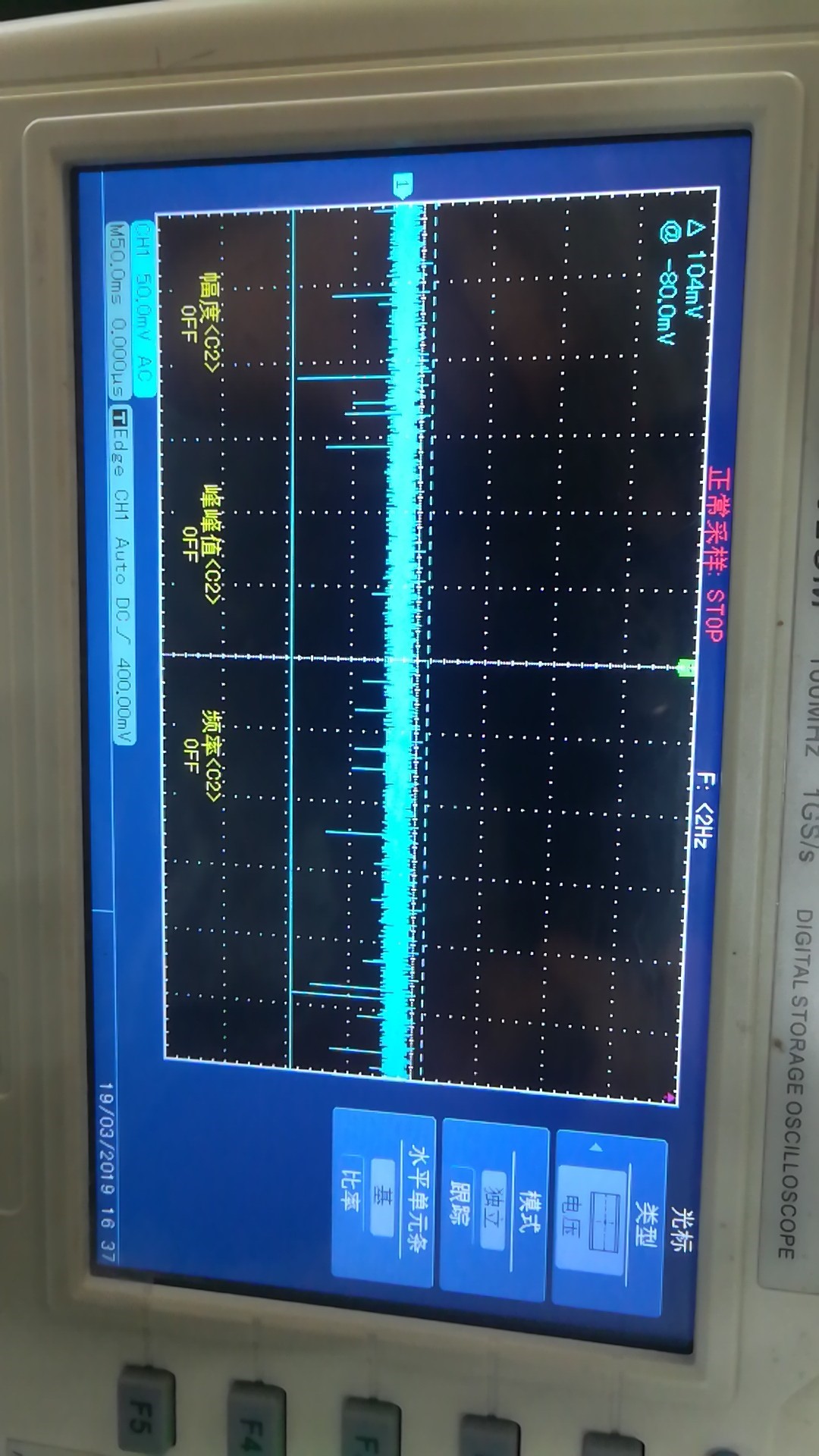
  • Thank you very much for your reply. Some test information is as follows

    VBAT pin ripple voltage is 25.6mv

    VBUS pin ripple voltage is 104mv

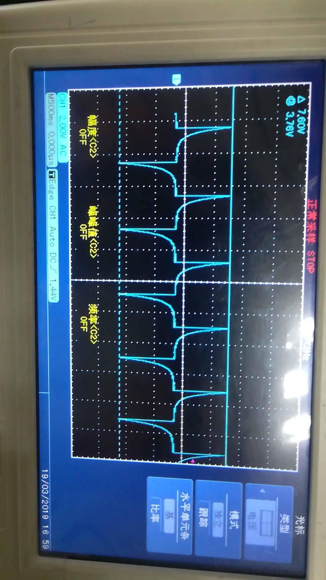
    STAT

  • Hi Allen,

    I'm unable to duplicate your issue on one of our EVMs.

    In the waveform below, I have a capacitor connected to the BAT pin, and I manually increase the voltage to simulate a battery being charged. You can see the charge current step up from 100 mA (trickle charge) to 480 mA (pre-charge) to 1.02 A (fast charge). The STAT pin stays low while the battery is being charged and only goes high after charging is complete and the battery has already reached 4.2 V.

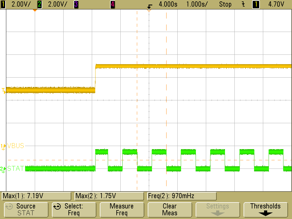
    I'm confused by your STAT waveform. Why does the voltage go negative? The STAT pin voltage should never go outside the range from 0 V to the pull-up rail, which is 5 V in your circuit. For example, in the waveform below, I increase VBUS to force an input overvoltage fault. The STAT pin voltage is a square wave that oscillates between 0 V and 1.7 V.

    Where exactly are you probing STAT? It might also be worth probing the 5 V pull-up rail just to make sure that something strange isn't going on there.

    Best regards,

    Angelo

  • Hi Allen,

    We haven't heard back from you. We are assuming you were able to resolve your issue. If not, just post a reply below or create a new thread if the thread has locked due to time-out.

    Best regards,
    Angelo