This thread has been locked.

If you have a related question, please click the "Ask a related question" button in the top right corner. The newly created question will be automatically linked to this question.

TPS7A8300: some questions about TPS7A8300

Part Number: TPS7A8300
Other Parts Discussed in Thread: TPS7A83A

Hi team,

we have some quesitons about TPS7A8300 below,

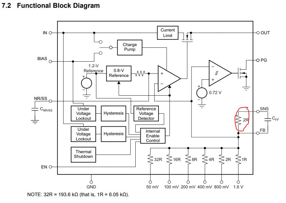
1.whether we can alwayas connect the SNS pin to OUT nomatter ANY-OUT or not?

2.for the bode plot test, how to test it? whether we only need to change the R6 to 100ohm,or we also need to connect like below.

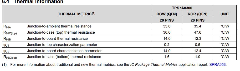
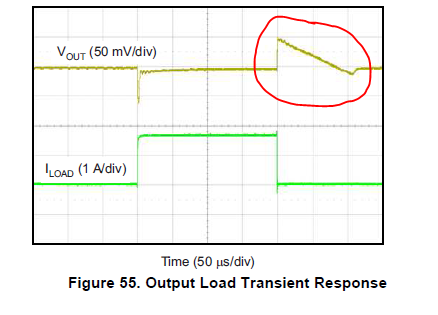
3. the datasheet low dropout voltage is 125mv at 2A, for the table below, 25°, 2A Vdo is larger than 160mv. for figure 55, why the Vout overshoot drop so slowly, whether it has connection with dropout voltage? If we use 240mv dropout voltage in a system, whether it's ok?

4. Can we provide Pd with temperature curve like below?

Thanks.

  • Hi Frank,

    1) The SNS pin should only be connected when using ANYOUT function of the LDO.

    This is because there is an internal resistor between SNS and FB that would cause your application to achieve an unintended output voltage when using external resistor dividers.  Please note that we do not recommend using the internal ANYOUT resistors and an external resistor divider at the same time.  This is because the internal ANYOUT resistors are trimmed so that the ratio between the resistors is accurate rather than the resistance.

    2) Unfortunately you cannot completely break the loop for TPS7A8300; therefore, a traditional bode plot is not possible.  In order to check stability for your application, we recommend monitoring the output voltage on a scope while performing load transients as described in the following Application Report:

    It is also possible to check stability by measuring the output impedance in your application as described in the following:

    3) Figure 55 is showing the load transient response of the TPS7A8300.  Keep in mind that traditional LDOs will not sink current.  As such, when a sudden drop in the load current causes the output voltage to overshoot, it is up to the load itself to discharge the output capacitors.  The lower load current will take more time to discharge the output capacitors.

    4) Your example curve is simply equation 10 from the datasheet (Tj = Pd x Rtheta_ja + Ta).  Rtheta_ja comes from the Thermal information table and Tj max for TPS7A8300 is 125 C.  As such, the curve for the RGR package will actually be the same as the one you provided.

    Please note that the pin-to-pin TPS7A83A does include a section on Recommended Area for Continuous Operation.

    Very Respectfully,

    Ryan