This thread has been locked.

If you have a related question, please click the "Ask a related question" button in the top right corner. The newly created question will be automatically linked to this question.

LM2611: The issue of LM2611

Part Number: LM2611

Hi,

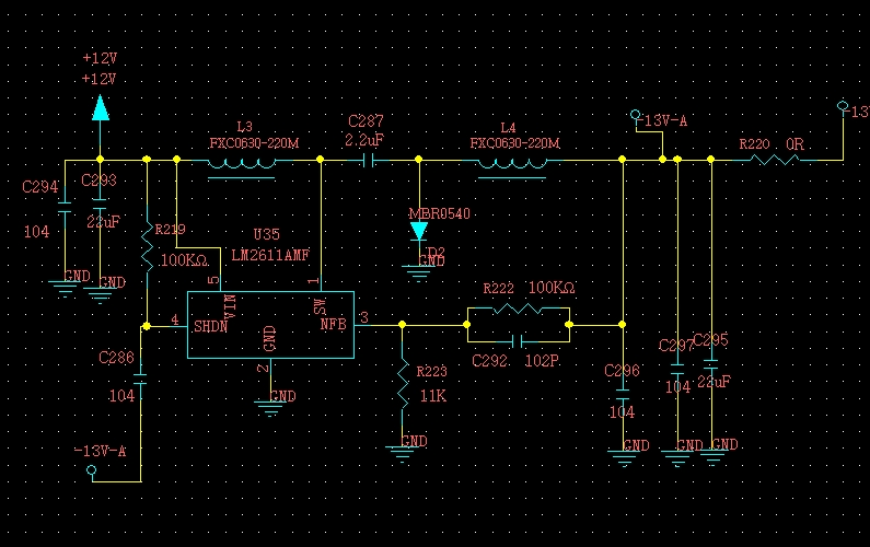
We refer to the soft-star schematic of LM2611 datasheet in our design, and the voltage is step up from 12V to 12.8V(input 12V and output 12.8V),

the PCB is short circuit when the power on, can you help to check the schematic and give us your suggestion, thanks?

The schematic for your referenc

e.

  • Hello user5973782,

    You mention that the voltage is step up from 12V on the input to 12.8V on the output. Is this the failure you observe? Your schematic shows -13V as output voltage, so I expect this is your desired output voltage, correct?

    The difference I can find compared to Figure 32 is the CUK capacitor C287 which is 1uF in the example in the datasheet and 2.2uF in your schematic, but I do not expect that this causes an issue.
    Are you using a coupled inductor or 2 separate inductors? (I expect as well that this is not a problem for your short.)

    How many PCBs do you have showing the short? Is this possibly a production issue of the PCB?
    Are you seeing a hard short or is there maybe just high inrush current causing the input voltage to drop?

    Is the problem gone when you remove R220?
  • Hi Brigitte,

    Very thanks for your quickly reply.

    The below is the answer of your questions:

    First, there is no problem which we measured output voltage is -12.8V, R222 is 100K and R223 is 11K, we would like to know the output voltage(-12.8V) reasonable or not?

    We can not find the reference in the datasheet.

    Second, I have changed capacitance of C287 to 1UF, there is no help.

    Third, I use fxc0630-220m /22UH/ 4A which integrated forming large current patch power inductor and the dimensions are 7*7*3mm.

    Fourth, The circuit is short out when power turn on, nothing to do for the PCB.

    Fifth, it is no help to remove R220, I have disconnected and tried with no-load.

    The inductance as below picture:

  • Hello user5973782,

    I am sorry, but I am a bit confused about the issue you have.

    1. -12.8V seems to be ok, because if I calculate with the given -1.23V feedback voltage and your resistors, I get to -12.4V. The difference in voltage is possibly caused by the resistor divider. It is mentioned in the datasheet that it is recommended to use values below 50 kOhm.

    2. You mention that there is a short when you turn on the power supply. What exactly does this mean. Is there more current on the input than you expect? How many boards do you have that show the problem?

    Does it change the behavior of the circuit when you remove the startup capacitor connected from /SHDN to VOUT?

  • Hi Brigitte,
    Thanks for your comment, I would like to check the schematic and material quality first.
  • Hello user5973782,

    Therefore I will close this discussion for the moment. If you have more information, either post again in this thread or start a new one if this one is locked.