This thread has been locked.

If you have a related question, please click the "Ask a related question" button in the top right corner. The newly created question will be automatically linked to this question.

TPS544B25EVM-681: Unable to Set >1.2V in TPS544B25EVM-581

Part Number: TPS544B25EVM-681
Other Parts Discussed in Thread: TPS546C23, TPS544B25

Setup:

Setup 1: EVM connected to PC via PM bus adapter

Setup 2: EVM connected to External Device via I2C Bus


Explanation:

Setup 1: When I put below parameters in EVM, it doesn’t set the output voltage to 1.8V and returns a NACK while it works till 1.2 V. Below is the screenshot before setting voltage and after clicking write to hardware

Figure 1: Before programming


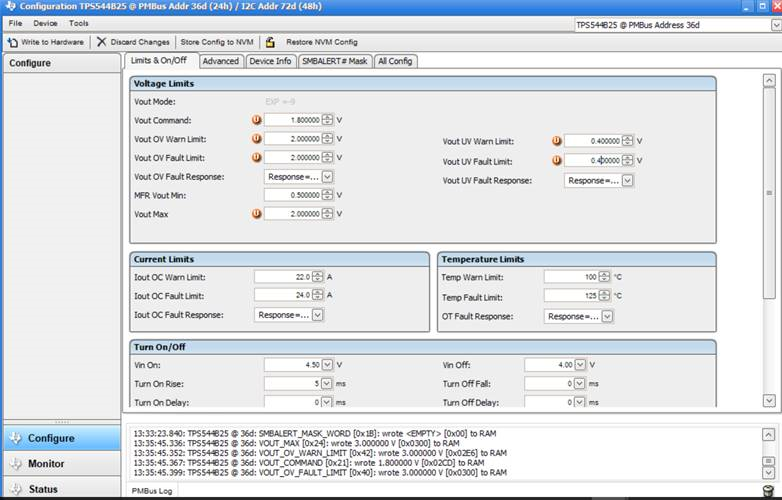
Figure 2 : After Programming


Setup 2 :

When the device is connected to External SoC via I2C and a linux C Code is written to send data, same thing is observed. Below is the programming sequence taken from data sheet used for writing the firmware 1) (40h) VOUT_OV_FAULT_LIMIT
2) (42h) VOUT_OV_WARN_LIMIT
3) (24h) VOUT_MAX (ordering with respect to VOUT_OV_FAULT_LIMIT and VOUT_OV_WARN_LIMIT is
irrelevant. Just set VOUT_MAX prior to VOUT_COMMAND)
4) (21h) VOUT_COMMAND
5) (A4h) MFR_VOUT_MIN (ordering with respect to VOUT_UV_FAULT_LIMIT and VOUT_UV_WARN_LIMIT is
irrelevant. Just set MFR_VOUT_MIN after VOUT_COMMAND)
6) (43h) VOUT_UV_WARN_LIMIT
7)  (44h) VOUT_UV_FAULT_LIMIT


Question:

How to set freq >1.2 V?

What command code has to be configured to what value for this?


  • Nishant,

    The EVM as configured will not support 1.8 V output voltage thru PMBus command alone.  It will require hardware modification.  As built, the EVM does not have a low side FB resistor, VOUT_SCALE_LOOP is set to 1 and VSET is pulled up to BP3, so the output will be regulated to the VOUT_COMMAND value set point, 0.950 V default value.  The set point range fro VOUT_Command is 0.5 to 1.5 V, so that is the adjustable range.  You can populate R9 with 11.3 kohm to change the default output to 1.8 V without any PMBus commands.  Other options are possible, depending on your specific requirements.  Let me know if this works for you.  The various other possibilities with hardware and programming changes are discussed in detail in the data sheet.  Contact us again if you have further questions.

  • Hi John,

    Thanks for the reply. My requirement is that my firmware which runs in linux should configure the voltage from 0.8 to 3.3V . However I am able to vary the voltage till 1.2 . So pls give me the solution to do this with pmbus command and not with hardware setup.

    Regards

    Nishant

  • Nishant,

    You will at a minimum need to populate a bottom side resistor divider. The set point ranges are 0.5 to 1.5 V (VOUT_SCALE_LOOP = 1), 1 to 3 V (VOUT_SCALE_LOOP = 0.5) and 2 to 6 V (VOUT_SCALE_LOOP = 0.25). None of those combinations cover your full range. Let me check if it is possible to work around this. It may take a while as the person who supports this just recently left the company.
  • Nishant,

    You will absolutely need to cross over VOUT_SCALE_LOOP boundaries. While you can spoof the TPS544B25 to output the voltage you desire, you will confuse the fault detection and telemetry as it will be expecting a different voltage than you are actually outputting. If you really need to scale from 0.8 V to 3.3 V, then a much better solution would be TPS546C23. The VOUT_SCALE_LOOP option of 0.5 will support direct scaling of the output via the VOUT_COMMAND over a range of 0.7 V to 3.3 V. Let me know if that will work for you.
  • Hi John,,

    Thanks. What are the resistor value for this to be pulled down for different VOUT SCALE LOOP? You mentioned previously about 11k pull down. Was that for 0.5 loop? Till you find a solution I will make my firmware by changing these resistor values.

    Regards

    Nishant

  • Nishant,

    This is has the potential to go down the rabbit hole. When you first posted, you stated you just wanted 1.8 V output, and that resistor suggestion was for a fixed 1.8 V output and the preset VOUT_SCALE_LOOP. That would get you the basic 1.8 V output without using any PMBus commands. For adjusting the output voltage using the AVS function from 0.8 V to 3.3 V using TPS544B25 requires crossing over two different VOUT_SCALE_LOOP settings. While that can be spoofed to work for basic Vout setting, you will have issues with the telemetry over voltage detection. The VOUT_COMMAND setting to get a specific voltage would be different than what is in the command table. You would get your desired output voltage, but TPS544B25 "thinks" it is programmed to a different voltage because you did not change the required resistor divider ratio as defined in TABLE 1. You would have to change both the VOUT_SCALE_LOOP setting AND the lower resistor divider (according to Table 1) to get accurate telemetry and fault detection since the 0.8 to 3.3 V range spans all three of the VOUT_SCALE_LOOP settings. I have some documentation I can share on that. Bottom line is that if you want a single hardware solution for 0.8 V to 3.3 V AVS adjust with consistent and accurate telemetry, you need to stay within a single VOUT_SCALE_LOOP range. Switching to TPS546C23 slves this issue as the 0.5 setting spans the range of 0.7 to 3.3 V which includes your whole range. So you can have a single hardware configuration. If you can either change the lower resistor (via digital potentiometer or FET switching) OR live with inaccurate telemetry, we can talk about the TPS544B25 approach. Let me know how you want to proceed. We should probably move this off line. I can be reached at j(dash)tucker(at)ti(dot)com. I will be off line until tomorrow after about 10 minutes tonight.
  • Hi John,
    Sure I will mail you offline. The title of the forum is >1.2V. 1.8V was just an example which I showed.

    Regards
    Nishant
  • Nishant.

    And you don't care about telemetry errors such as over or under voltage faults? or invalid command warnings? I really very strongly recommend TPS546C23 for your application. The implementation is straight forward with no work arounds. Let me know and I will work this tomorrow.
  • John,
    I doubt if that would be true. I can talk to my manager about that. However, do provide a solution for that too which I can propose them.

    Regards
    Nishant
  • Closing this to resolved, as we are using switch to control the loop with various resistor combination.

    Thanks John for your support.