Good day.
I would like to check if the current waveform of shim inductor is right because it is different compared to your evaluation board.
I had tried to modify the inductance, core materials, core size and winding thickness due to overheating of the shim inductor, but it makes no odds.
If our current waveform is a problem, please let me know how to figure it out away.
----- **Developement dails. **---------------------
Input: 350-410V, typical 390V
Output: 28V/1KW
Switching Frequency: 200Khz
Transformer turn ratio 9:1
inducance : 1.1mH
shim inductance : 20uH
---------------------------------------------------------
Evaluation board's waveform.
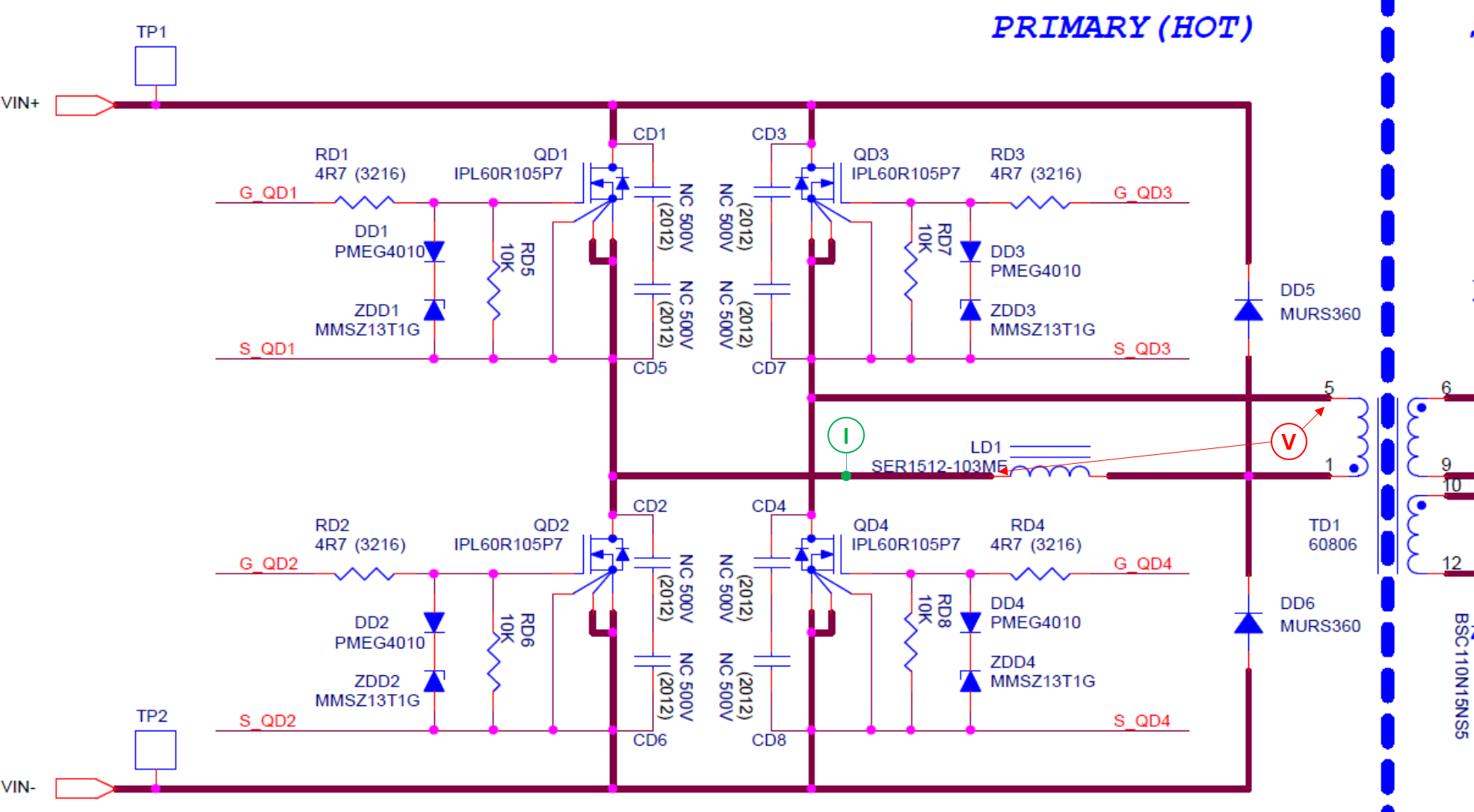
C2 is voltage across transformer, C4 is curent of shim inductor
![]()
Our board's wafeform.
C2 is voltage across transformer, C4 is curent of shim inductor
![]()
Best Regards