This thread has been locked.

If you have a related question, please click the "Ask a related question" button in the top right corner. The newly created question will be automatically linked to this question.

LM5088: Compensation in Current Mode SMPS

Part Number: LM5088

Hello,

      I am trying to use the LM5088 in a project of mine. And this led to me read a bit more about current mode control in SMPS. Thus, my question pertains to current mode SMPS in general. I was reading this application note from TI for more information on Current Mode control

https://www.ti.com/seclit/ml/slup340/slup340.pdf

I have a few questions in this regard

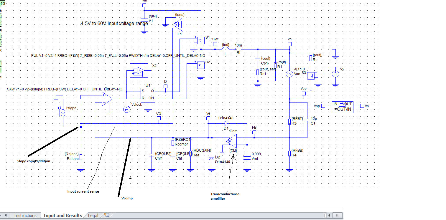
1. Figure 16 shows the schematic of the current mode Buck. As per the schematic, you are using the inductor current to generate the PWM ramp. However, it seems you are using the load current in this ramp generaton as well. This means that the ramp generation is load current dependent. This means that the duty cycle will have a large load current dependency. This does not look correct. Can you please clarify if this is indeed so?

2. Secondly, in the same Figure 16, you show an external ramp in order to prevent subharmonic oscillations. Is this external ramp related to the inductor current ramp in anyway or is it completely independent? If it is completely independent, then surely it is interfering with the natural feedback mechanism of the loop and reducing the effectiveness of sampling the inductor current. Can you please clarify if this external ramp actually reduces the stability of the loop? 

3. Finally, you talk about poles and zeros transfer functions in equations 22-26. Can you please clarify if these poles and zeros are closed loop poles and zeros or whether they are open loop poles and zeros? 

Thanking You

Sanjay

  • Sanjay ,

    below is how the simple peak current mode control looks like :

    So in short there are two loops ie slower voltage loop at the output and faster current loop  which reset the flip flop and the the high side FET is turned off . 

    Here are some of the papers you can read to understand the current mode functioning further .  http://www.tij.co.jp/jp/lit/an/snva555/snva555.pdf 

  • 1) The equations associated with figure 16 are for a continuous conduction mode CCM buck converter. Therefore the duty cycle is independent of load, the duty cycle is equal to Vout/Vin. The average of the inductor current ramp moves up and down depending on load, so the peak to peak inductor current ramp and duty do not change for load in a CCM buck converter.

    2) The slope compensation ramp is related to the inductor current, and there is an equation in the LM5088 data sheet ( look at section 9.4.4). We also give an equation in the referenced paper EQ. 27 which shows the relationship. Please read through section 9.4.4 carefully. The benefit of a current mode feedback buck, is that it splits the complex congregate pole (found in a voltage mode buck) into a single high and low frequency pole. This helps to get more phase margin and bandwidth, which in turn gives better transient response. The catch is if the slope compensation ramp is too big, then it could force the converter into voltage mode feedback, and you lose the benefits of the current mode feedback. Therefore you need to set the slope compensation ramp big enough to negate sub-harmonic oscillation, but not too big as to force the converter into voltage mode feedback.

    3) The poles and zeros refer to a closed loop response.

  • Dear Ambreesh,

    Thank you so much for your explanation, the simplified schematic and the references. I am still going through them and evaluating your answers. There is so much material here. It will take me some time to get the answers I am seeking or to come up with new questions. Once I am done, I will either add new questions or else, I will click the Issue resolved button.

    Thanking You
    Sanjay
  • Hi Lou,

    Thank you for your simple, easy to understand explanations. I am still evaluating both your and Ambareesh's answers and considering the implications for my design. Since I have not worked with SMPS in a while, and have never worked with current mode control, it is taking me some time to come to grips with all of this new information. Please be patient with me. If this resolves all my issues, I will certainly click the appropriate button.

    Thanking You
    Sanjay
  • Dear Lou/Ambreesh,

    Thank you for your lucid explanations. I think I finally understand. All my questions are now answered. Thank you very much.

    Warmly
    Sanjay