This thread has been locked.

If you have a related question, please click the "Ask a related question" button in the top right corner. The newly created question will be automatically linked to this question.

BQ24715: BQ24715 can't charge the deeply Discharged Battery issue

Part Number: BQ24715
Other Parts Discussed in Thread: BQ40Z50

HI Sir,

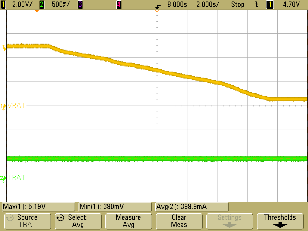
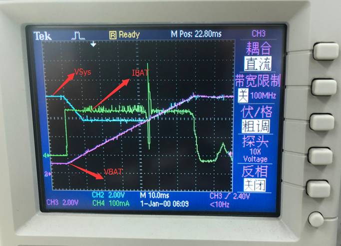
     my customer used TI BQ24715 for 2s Battery charging, now the battery discharged to deeply discharged( the battery Discharge cut-off voltage is 6V set by the battery protection board ). as the battery has about 0.4mA Quiescent Current,  so the 2s cell voltage will drop down from 6V to 2V. when  the 2s cell voltage drop down below 3.6V, The bq24715 can't active  the battery pack to charge.

     but the DC power supply  can active the batter pack to charge.  so customer confused that  why the DC power supply can active the 2V cell  Battery ,but the  BQ24715 can't.  please give me some suggestion to debug,TKS.

  • Hi Jerry,

    Just to clarify, what is the charge current when VBAT < 3.6 V? What are your customer's charge current and minimum system voltage register settings?
    Instead of the battery pack and battery protection board, does the issue still exist if a capacitor is connected to BAT in order to simulate a battery?
    Also, is your customer using one of our EVMs or his/her own circuit?

    Best regards,
    Angelo
  • hi Angelo,
    when the VBAT is under 6V , the Battery PACK will enter into discharged protection mode. when VBat <3.6V, the charge current is 0 A by measure the Volltage across the SRP and SRN of sense resistor . the register seetings of charge current and minimum system voltage is about 2A(charge current) and 5.88V(minimum) .
    we can see that after the battery pack enter into discharged protection mode. if the cell voltage is above 3.6V , the BQ24715 can charge battery with 200mA charge current. but if the cell voltage is under 3.6V, the charge current is 0V. we try to use electronic load instead of battery pack. it's seem to no use. the charge current is 0 A.
    all of the test is based on custoemer their own circuit.
  • Hi Jerry,

    I was unable to duplicate this issue on one of our EVMs.

    In the waveform below, I manually decreased VBAT down from 5 V to simulate a battery discharging, but the pre-charge current stayed constant and never dropped to zero. I used a 20 V adapter for VIN and a 2200 µF connected to BAT.

    Do you have BATFET LDO mode enabled or disabled? That can affect the pre-charge current threshold, as shown in the graph below:

    Best regards,

    Angelo

  • Hi Angelo,
    you can try to set the VBAT under 3.6V , you will see there is no current go through the sense the resistor. customer set BATFET Enter into LDO MODE, It's no use
  • Hi angelo,

        please help to refer the wave of BATFET Gate pin and drain pin when the Cell Voltage is under 3.6v

  • Hi Jerry,

    Even with VBAT < 3.6 V, I'm definitely able to apply a pre-charge current of almost 400 mA.

    Can you please capture a waveform with the following information: VBAT, IBAT (if you don't have a current probe, then the voltage across the sense resistor is fine too), VSYS, and PHASE? Please use a capacitor connected to the BAT pin instead of the battery pack and battery protection board. I'd like to see the behavior as VBAT is decreased from 7 V down below 3.6 V (similar to the waveform I sent earlier).

    Best regards,
    Angelo
  • Hi Angelo,

         please  help to find the waveform customer captured.

  • Hi Jerry,

    Thanks for sending that waveform; it definitely helps provide a better understanding of the issue. There's lots of unusual behavior in the waveform you sent. A couple questions:

    1) Is the charge current register still set at 2 A? With LDO mode enabled, once VBAT > SYS_MIN, then IBAT should jump from 384 mA pre-charge current up to the charge current setting. The IBAT = 250 mA level shown in your waveform doesn't make sense if the charge current register is still set at 2 A.

    2) Is your customer testing this with a system load connected? Based on VSYS starting at 8.4 V as well as the IBAT behavior, it looks like there must be a system connected. Please try doing the same test again, but with no system connected this time. Hopefully this will help us isolate what's causing the issue so we can determine whether the culprit is the charger circuit or whether it's something else in your customer's design.

    For reference, here is the expected behavior with the customer's register settings (LDO mode enabled, charge current = 2 A, SYS_MIN = 5.88 V). I have a 2200 µF capacitor connected to BAT, and I'm using a Kepco bipolar power supply connected to the capacitor in order to manually increase and decrease VBAT. Yellow is VSYS, green is VBAT, and purple is IBAT:

    There are two regions of operation here:

    1) When 0 V < VBAT < SYS_MIN (5.88 V): The charger applies 384 mA pre-charge current. The BATFET operates in LDO mode, and VSYS is regulated above SYS_MIN.

    2) When SYS_MIN < VBAT < max charge voltage (8.4 V): The charger applies 2 A fast charge current. The BATFET is fully on, so VSYS = VBAT.

    If your customer's behavior still doesn't match the waveform above when testing with a capacitor connected to BAT and no system connected, then there's most likely an issue with their charger circuit, and that would be the next thing to debug.

    Best regards,

    Angelo

  • Hi Angelo,


          Yes , there is a System load connected the Vsys  Pin. But It's hard to disconnected  the Vsys Voltage completelly as it will provide power for MCU which will set  BQ24715 Register Via SMBUS.

    customer  did a new test using another Battery pack(BQ40Z50 Gauge inside) as below:
    1. Disable BQ24715 LDO mode, Pre-charge current is set to 75mA by BQ40Z50 Gauge.
    2. connect  19V power Supply to customer's PCB with battery pack,
    3. we can see that there is only 35mA current output from the 19V power supply, if we turn off the System load,meantime, it's seem to BQ24715 enter into DCM mode, there is also no cuurent to battery pack.
    4. if we turn on the system load, there is about 300mA current output from the 19V Power supply, the BQ24715 enter into CCM mode from DCM mode, and we can see there is 50mA Current to battey pack.

     based on above behavior, my quesntion is that.
     1. if disable LDO mode, the pre-charge current is set by battery pack. under this mode,it's seem to BQ24715 is very easy enter into DCM mode .it will effect BQ24715  charge
     2. if enable LDO mode, the pre-charge current is set by BQ24715  charge current Register ,but Gauge BQ40Z50 also will set pre-charge current.  which is prior for them ?

  • Sorry attached turn off system load waveform  as below:

    the blue channel is the lowside MOSFET of BQ24715 Waveform.

  • Hi Jerry,

    Yes, under light load conditions (such as when the system load is turned off), the BQ24715 will turn off the LSFET in order to avoid negative inductor current. With the default value of Rac = 10 mΩ, the LSFET is turned off when the input current falls below 125 mA. This explains your observation that the converter changes from DCM to CCM operation when the system load is turned on, which causes the input current to increase from 35 mA to 300 mA.

    If LDO mode is enabled, then the pre-charge current is set by the charge current register and is clamped below 384 mA. In other words, IPRECHG = ICHG for ICHG < 384 mA, and IPRECHG = 384 mA for ICHG > 384 mA.

    Best regards,
    Angelo