This thread has been locked.

If you have a related question, please click the "Ask a related question" button in the top right corner. The newly created question will be automatically linked to this question.

LM5176: Buck-Boost Circuit, 12 V 16 A output: In Buck Mode, Vout ≈ Vin+0.5 V, not 12V regulated

Part Number: LM5176
Other Parts Discussed in Thread: CSD17577Q5A, CSD17573Q5B, CSD17303Q5

I am testing the circuit found here. I printed PCBs and hand-soldered the components; there may be some poor solder joints I need to re-visit, but I'm trying to figure out where to start.

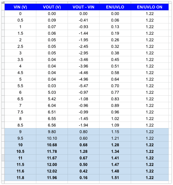
Right now when I ramp the voltage up, the output voltage tracks as follows:

Questions:

  1. What would cause the output to sit around 0.5-1.0 V above VIN, rather than at 12.0 V as specced by the feedback resistors? Where can I probe to get to the root cause?

The circuit turns on earlier than expected (when UVLO is higher than 1.22); the specced resistors set it for ≈ 10 V. But I measured on the pin and at 9 V, EN/UVLO measured was > 1.22 V so this is working as expected. Maybe a component issue.

  • Also, I should add that with any significant load >0.100 mA, the output drops down to almost 0.00V
  • Hi Jim,

    Thank you for considering the LM5176. The Webench schematic looks okay but it does missing a 2K resistor at the VISNS pin. Please refer to the datasheet. This is a flaw of Webench modeling and we are in the process to correct it, although it does not cause your current problem. Just for your information.

    Like you mentioned, there must be some errors in your circuit. If you would like, you can order an EVM and do the evaluation.

    To debug your circuit: it seems the boost leg is not switching which it is suppose to boost from the lower VIN.

    Please monitor FB pin voltage. It should always be in proportional to VOUT. Otherwise you may have soldering problem of the feedback resistors.

    You need also to monitor the COMP voltage. It should stay high because your output is under regulation. If not, check the components connecting to the COMP sisignal.

    Also check your MOSFET soldering, especially the gate of M4. When Vin<Vout, it must has switching pulses.

    Double check the soldering of your IC.

    Thanks,
    Youhao
  • Thanks Youhao. It does seem to have been a soldering problem, and is working ok now.

    Regarding the 2K resistor from VISNS, what is this resistor for? What happens if VISNS is direct connected to V(in)?

  • Hi Jim,

    Thank you for the updates, and I am glad that your circuit is working now.

    The 2k resistor is for protection. During the development of the LM5176 we found the VISNS requires a 2k resistor to protect the pin under all operating conditions. Please following this recommendation.

    Best Regards,
    Youhao
  • Thank you . I have two follow up questions, for the same design, albeit different issues:

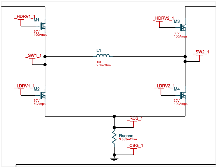
    1. Can the FET selection be simplified such that we use 4 of the same FET? The Power Designer tool gives 3 different FETs, with similar specs:
      1. CSD17303Q5 - 30V 100A (M1, M3)
      2. CSD17577Q5A - 30V 60A (M2)
      3. CSD17573Q5B - 30V 100A (M4)

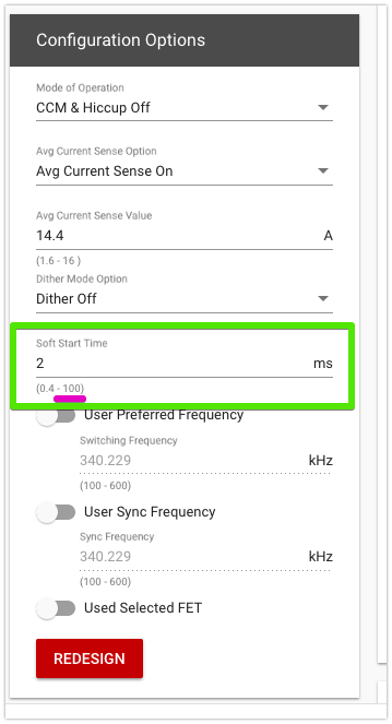
    2. In the Power Designer tool, the max soft start time is given as 100 ms. Is this a hard limit? Can we go longer? I have a heavily capacitive load, so would rather slow down the start up time to minimize inrush current.

  • Ideally, we would use 4x CSD17573Q5B -- would that work? If not, what about 4x CSD17303Q5?
  • HI Youhao Xi (1880260) , in regards to the VISNS resistor, I checked the datasheet and my understanding is this is only needed at V(in) > 40 V. So not for my application. Am I misunderstanding something?

    From section 8.3.7:

    "For application where input voltage is higher than 40 V, a 2 kΩ resistor in series with the VISNS pin is required as shown in Figure 25."

  • Hi Jim,

    You are right it is recommended for >40V, but it would not hurt if your nominal voltage is lower. To be safe to against accidental high voltage attack, I would recommend you to have it on your circuit.

    Thanks,
    Youhao
  • Thanks Youhao Xi (1880260)... What about my post from Mar 26, 2019 2:35 PM?

    1. Can we simplify the BOM and use 4 identical NMOS FETs? If so, which do you recommend?
    2. What is the max soft-start time we can program with CSS? The design tool says 100 ms, is that the limit? I don't see it specified in the datasheet.

  • Hi Jim,

    1. Yes you can use 4 identical FETs. People usually choose different MOSFETs to get some incremental improvement of performance vs cost. But all FETs can be identical.
    2. I don;t think the design tool sets 100ms as the limit. I just checked and you can put larger numbers. However, 100ms very long for many applications. T I usually see spec of 1ms to 20ms.

    Thanks,
    Youhao