This thread has been locked.

If you have a related question, please click the "Ask a related question" button in the top right corner. The newly created question will be automatically linked to this question.

TPS2660: eFuse - fault signal sensitive to input ripple

Part Number: TPS2660

Hi,

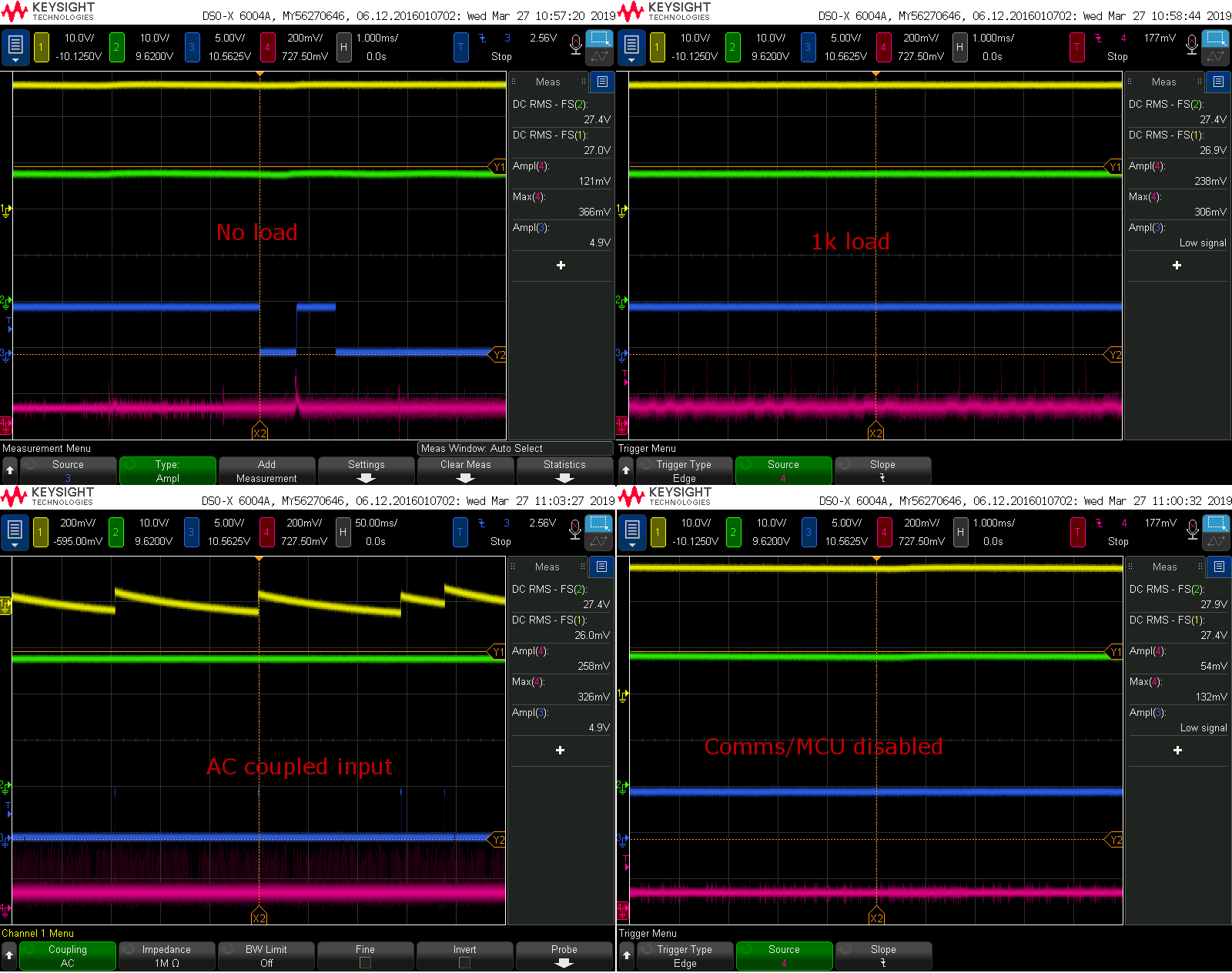
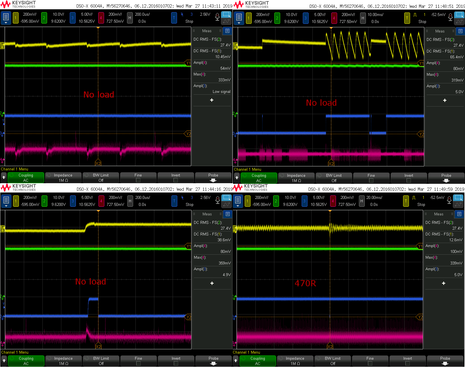
I have an issue with a TPS26600. The fault signal activates when it shouldn't. The device itself is operating as it should. The output is always on, limiting current and properly activating the fault signal when e.g. a short is present. The misbehavior of the fault signal only happens with no, or a very low load on the output < 5-10 mA. As soon as I apply some load the fault signal is stable high, as it should be.

Does this failure mode sound familiar in any way?

I have strapped OVP and UVLO to RTN, but also tried other configs, like a resistor divider setup, or UVLO strapped to the input, but no difference.

I have also tried to supply only this circuit in the design with a separate external PSU, operating at the same voltage, while the rest of the board is running normally. Then it seems to behave. The rippel on the supply on the design (~27V) is around 150mV, major component is in the ~1kHz range. But I can't understand why the circuit behaves like it does.

  • Hello Thomas,
    Can you provide the schematic for TPS26600 and waveforms of VIN, VOU, FLTb and IMON pins when FLTb pin toggling? This would help in understanding the cause of this behavior.
  • Hi,

    Attaching some scope plots and schematic snippet. This device is used 3 different places on the board, with slightly different current limits (0.35A to 1.2A), and they all behave in a similar way.

    • Channel 1: DC input
    • Channel 2: DC output
    • Channel 3: Fault signal
    • Channel 4: IMON

    One observation. In the 3rd plot (AC coupled) it seems the fault signal is triggered with the positive edge (~100mV) of the input ripple(?)

    Various plots with AC coupled input, with various things going on:

    Worst case RTN vs GND, and DVDT.

  • Thanks Thomas for providing with scope shots. It appears that FLT pin is triggering with ripple voltage input on IN pins. This could be due to triggering of fast trip comparator on positive transient on IN or due to triggering of Reverse comparator on negative transients.

    Below are few recommendations:

    • Increase the cap C1866 on IN pins to reduce ripple/transients. A small inductor can also be added in series at input to provide filtering of ripple and transients.
    • Increase ILIM by reducing R1855. (if permissible by other design requirements)
    • Reduce output cap C1874 (if permissible by other design requirements)

    Let us know if you have any further queries.