Because of the Thanksgiving holiday in the U.S., TI E2E™ design support forum responses may be delayed from November 25 through December 2. Thank you for your patience.

This thread has been locked.

If you have a related question, please click the "Ask a related question" button in the top right corner. The newly created question will be automatically linked to this question.

UCC28740: How to Disable Function for UCC28740 was safety, Primary-Side or Second-Side

Part Number: UCC28740
Other Parts Discussed in Thread: TL431

Dear,

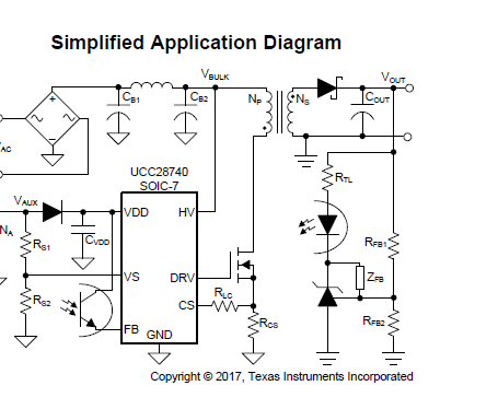
our system block as below chart and Flyback was use TI UCC28740, but we have two question about Energy saving.

1. how to disable function for UCC27840 in Primary-Side ( FB pin to low?  turn on OVP?)

2. how to disable function fot UCC28740 in Second-Side ( Rfb2 or Rtd1?)

Standard circuit:

system function block:

If any suggestion, Please advise me.

Thanks,

Best regards,

Lawrence.

  • Hello Lawrence,

    Thank you for your interest in using the UCC28740 flyback controller.

    To disable the controller on the primary side, you can either:
    a) force VS input high to simulate an over-voltage,
    b) force FB high to simulate "no-load" output condition, or
    c) force CS high to simulate a peak over-current condition.

    All 3 cases would be done using a "pull-up" transistor (PNP or PMOS) to VDD, but each pin (VS, FB, CS) has a different maximum voltage spec. The pull-up transistor would be triggered by some Enable/Disable circuit, and its collector or drain would include current and voltage limiting components to raise the chosen input to its respective over-load level, but protect it from excess voltage. (Abs Max ratings are VS < 7V, FB < 7V, CS < 5. Voltages needed to cause a fault are VS > 4.6V or CS > 1.6V. FB current > 35uA will drive switching frequency to minimum and will probably "starve" the VDD cap of charge. )

    To disable the controller from the secondary side, you can
    d) connect the cathode of the TL431 regulator to output GND, or
    e) use another opto-coupler to do the same thing as (a) or (c).

    I think that (d) is the simplest option if you want a secondary-side disable circuit.

    In all 5 cases, the UCC28740 will enter a UVLO-shutdown-and-retry cycle to attempt to restart over and over again, until the Disable signal is removed. There is no latching function to prevent restart attempts. However, the input power under this UVLO-cycling condition is so small that it still accomplishes a tremendous energy savings.

    Regards,
    Ulrich