This thread has been locked.

If you have a related question, please click the "Ask a related question" button in the top right corner. The newly created question will be automatically linked to this question.

LM5116: LM5116 overcurrent protection and short circuit problem for help

Part Number: LM5116

Hello, TI's expert:

        I am using LM5116MHX to make an 18-60v input and three-way output BUCK power supply.The output parameters are 5V 4A, 12V 3A, 12V 3A.Under different input voltages, the functions of output overcurrent protection and short circuit protection were tested. It was found that under certain input voltages, the output current during short circuit could only be limited to the set overcurrent point without burping protection. The BUCK inductance would have saturation risk.The minimum pin voltage of LM5116MHX UVLO was measured with an oscilloscope and the minimum value was found to be greater than 200mV. It was suspected that there was something wrong with the RAMP compensation circuit. As described in page 16-17 of the data table, the RAMP capacitance was adjusted by using WEBENCH POWER DESIGNER and a resistance was added between VCC and RAMP to increase RAMP compensation.The following figure shows the UVLO and output current waveforms I measured at different input voltages.Attached are the schematic diagram and PCB. Could you help me analyze this problem in detail?Looking forward to your early reply, thank you very much!

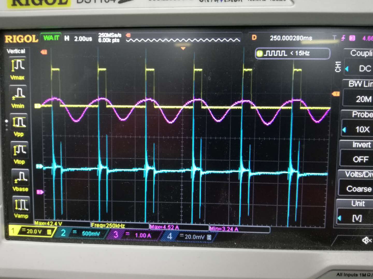
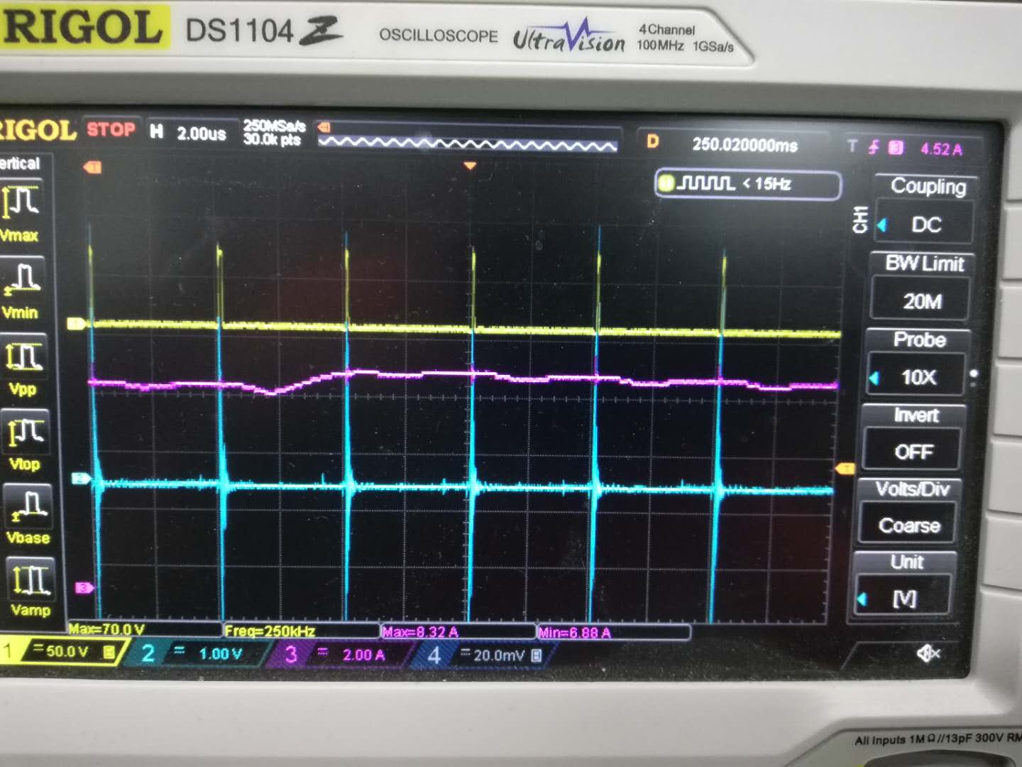
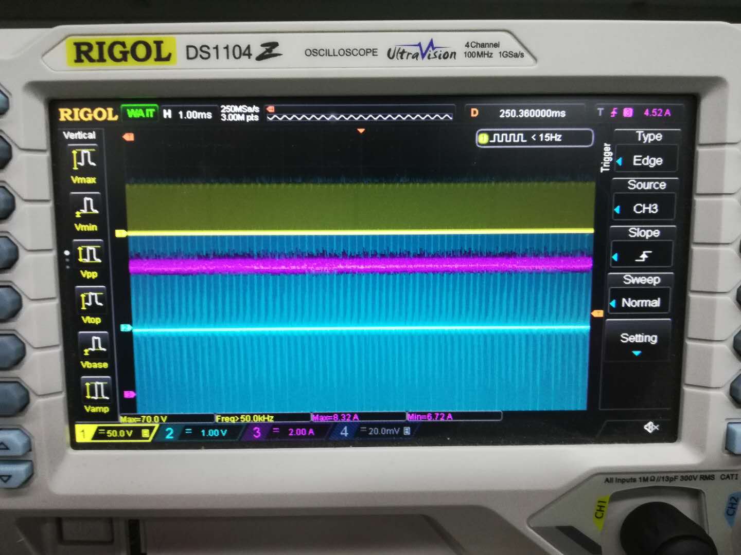
(1) 30V input 5V output short circuit, UVLO and output current waveform

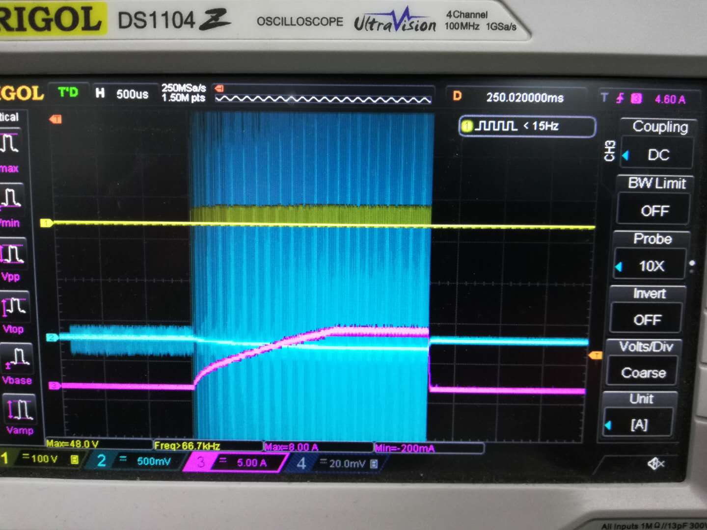
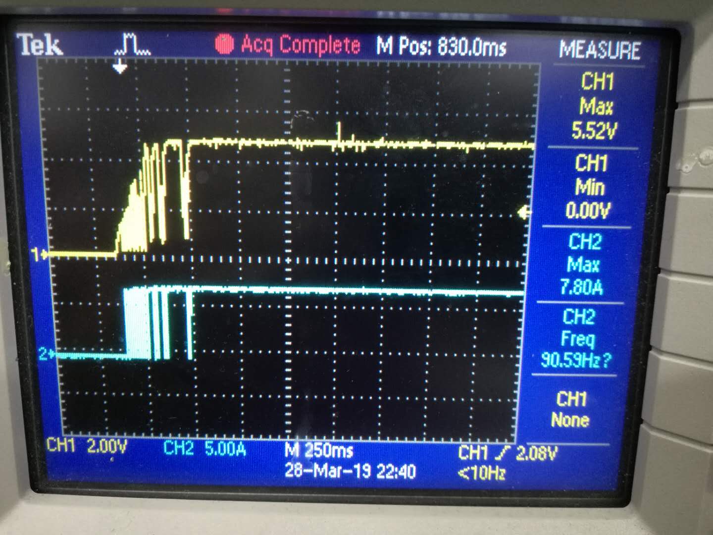
(2)30V input 5V output short circuit, boot instant UVLO and output current waveform


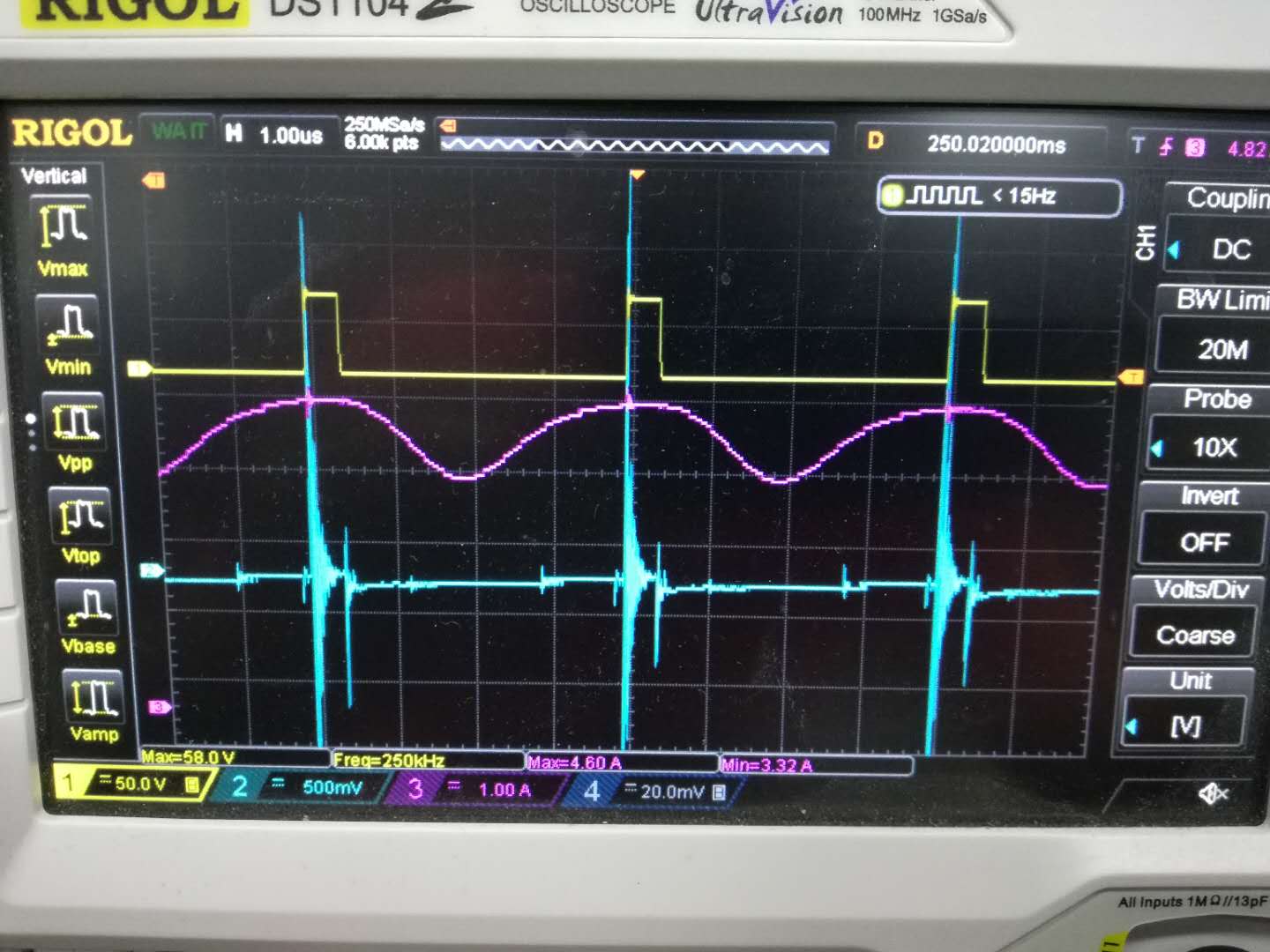
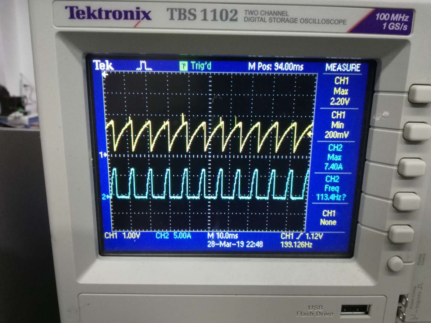
(3)45V input 5V output short circuit, UVLO and output current waveform


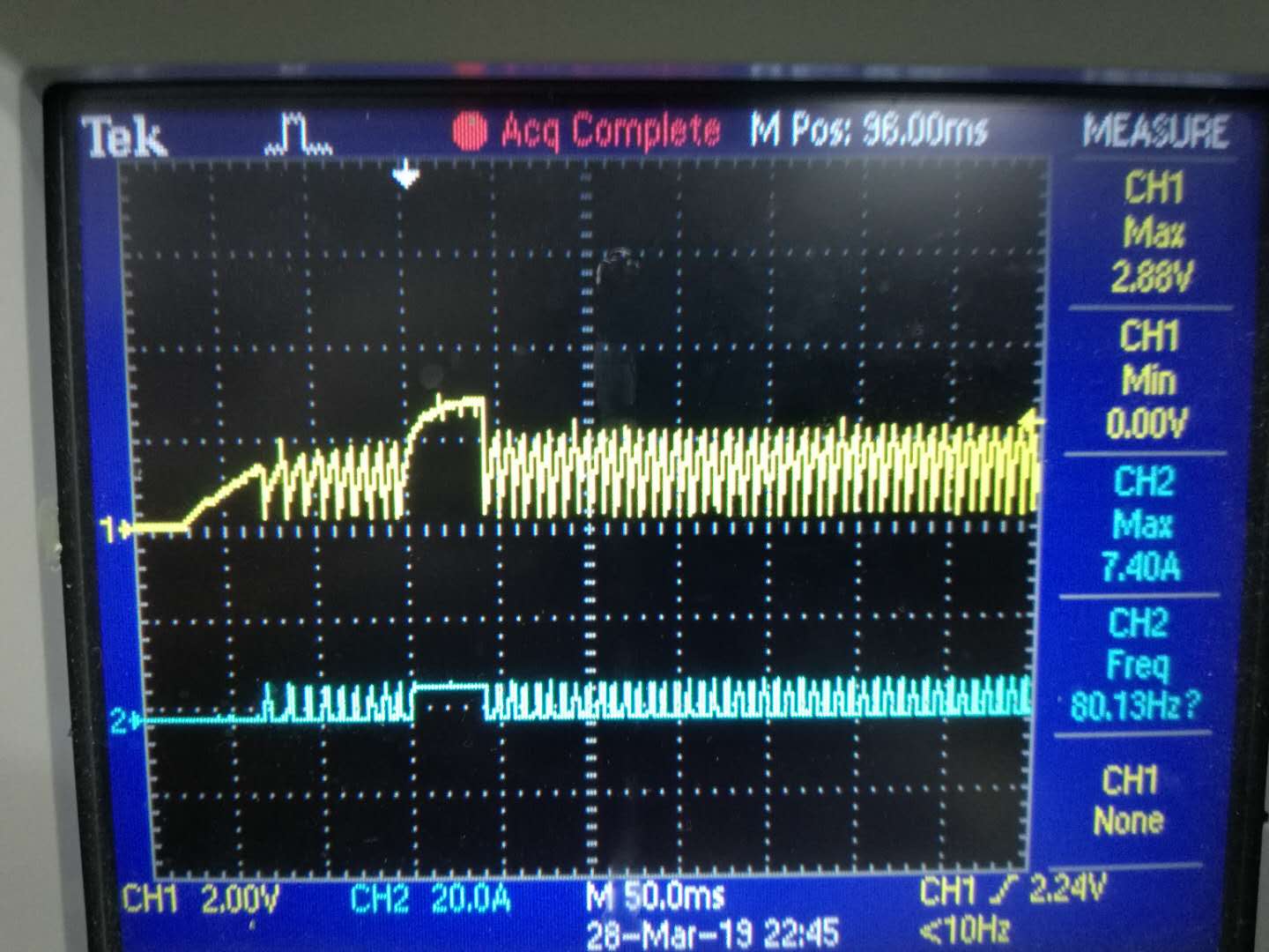
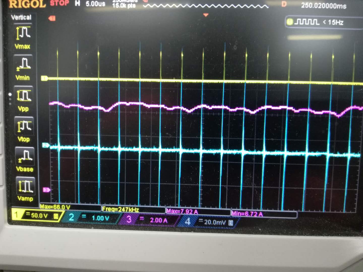
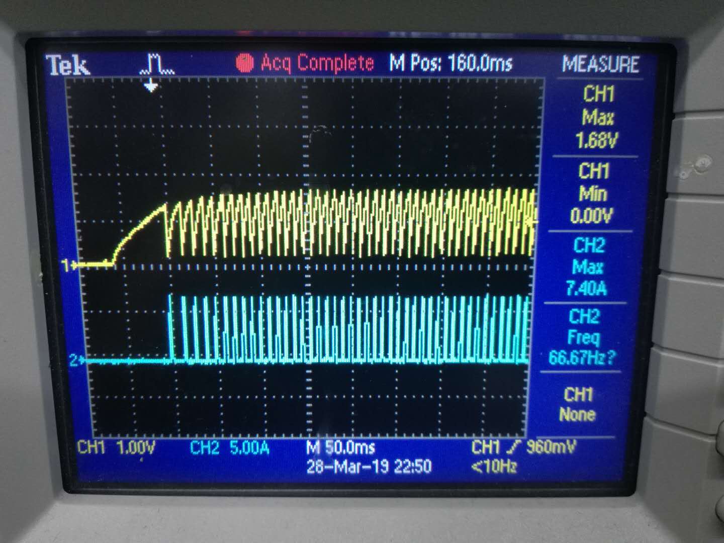
(4)58V input 5V output short circuit, UVLO and output current waveform


(5)Schematic diagram

6428.YOGO_POWER_V1.pdf

  • Hello,

    Please can you provide the Inductor current waveforms and the Switch node waveforms. Also please provide voltage measurement of the CS and CSG and also can you confirm that the CSG is not connected to ground at the IC.
    Thanks.

  • hello,David Baba:

                 I have measured the following waveform as you said.Channel 1 is the  yellow waveform of  SW to GND;Channel 2 is the green waveform of CS to CGS or GND;Channel 3 is the purple waveform of inductive current.

    (1) waveform tested when 30V input is 5V with 4A output


    (2) 30V input 5V short circuit test waveform,Short circuits can cause hiccups

    (3)waveform tested when 49V input is 5V with 4A output

    (4) 49V input 5V short circuit test waveform,Short circuits can't cause hiccups


    (5)waveform tested when 58V input is 5V with 4A output

    (6)58V input 5V short circuit test waveform,Short circuits can't cause hiccups

    PCB

    7624.PCB.zip

  • Hello ,

    The indutor waveform does not look correct? Should be measured before the output capacitor and should look like a triangular waveform? Also I am interested in seeing these waveform at the anomaly point, not during normal oration. As it appears the waveform's provided (apart from the inductor current) look normal?

    Thanks.
  • Hello Dong,

    I had not heard from you in a while. I will close thread. If you still have an issue, please feel free to reopen.

    Thanks.