This thread has been locked.

If you have a related question, please click the "Ask a related question" button in the top right corner. The newly created question will be automatically linked to this question.

TPS43060: Abnormal switching frequency issue

Part Number: TPS43060
Other Parts Discussed in Thread: LM5122

Hi teams

My customer is using TPS43060 for new design and encounters some issue.

Customer design requirements is 12V-30V 10A output.

The issue phenomenon:

  1. They connect a 470Kohm resistor in RT pin to set the switching frequency to 122Khz but the actual switching frequency only the 1/2 of calculation. Are the formula in data sheet is correct or wrong?
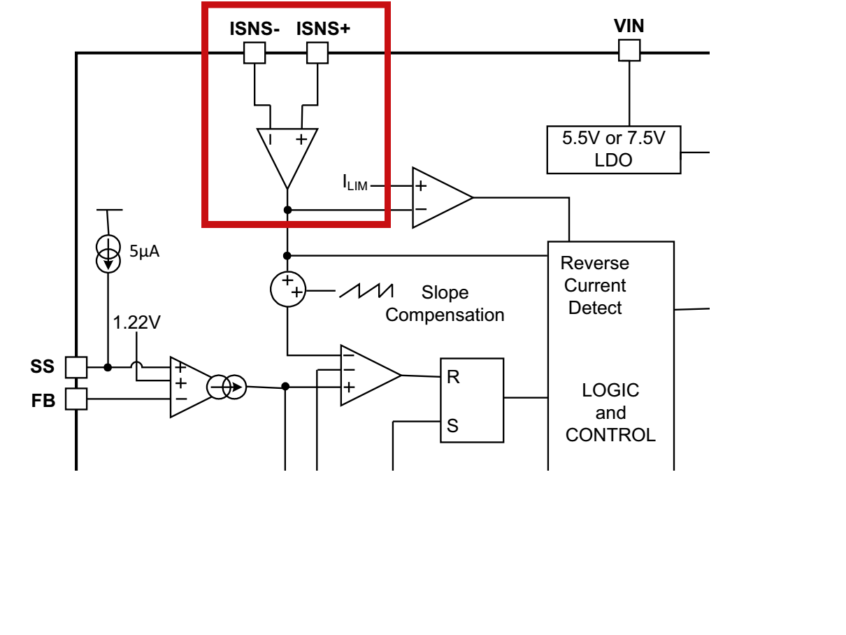
  2. I wondering to know the gain of the current sensing resistor amplifier. Datasheet didn't give this parameter.
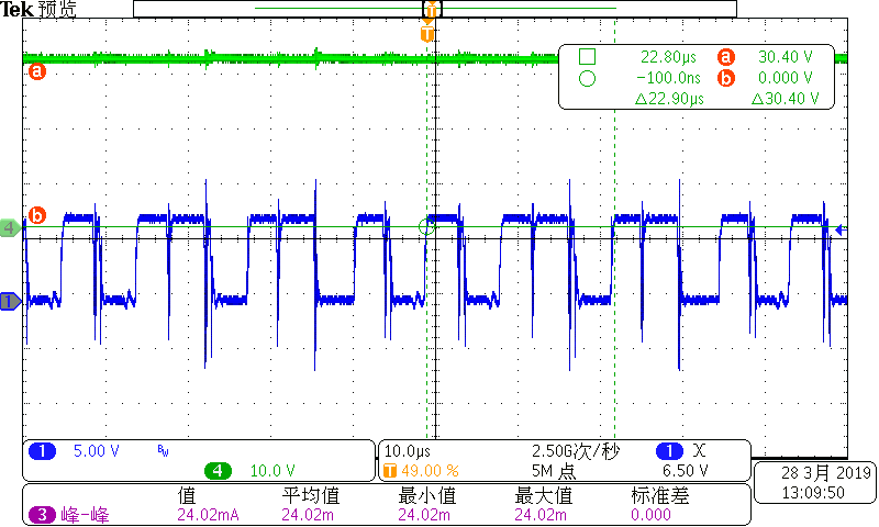
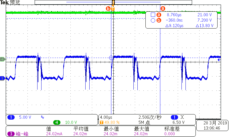
  3. The switching frequency becomes unstable when in higher load (2A). And the gate drive signal is also abnormal.
  4. What waveform we should seeing in RT pin when its normal? (If you can capture a picture is the best)
  5. Do our boot cap have UVLO protection? What's the threshold and machanism?

The and abnormal wavefrom is shown below: 

The schematic parameter:

  • Hi Gabriel,

    The datasheet is correct, and your circuit also operates at 122kHz. You seemed being misled by the waveforms. They actually two pulses together, one small and one big.

    Obviously your circuit does not have adequate slope compensation. A quick way to resolve this is to increase your inductor, or reduce the current sense resistor.

    Thanks,
    Youhao Xi, BCS Applications Engineering
  • Hi Youhao

    The waveform you have seem is capture after I replace the RT to 240Kohm which will set switching frequency to 244Hz in calculation.
    As customer is very urgent for this case, may I have a quite call with you to discuss this?
  • Youhao

    Another question we facing is the output voltage drop during the load increase.
    I have measure the COMP pin and it already been regulator to maximum clamp voltage 2.1V but the output voltage still can't reach the target value. It seems something limiting the duty cycle.
    We have try to reduce sensing resistor. But it didn't work.
  • You need to get the circuit stable first. Your circuit is not stable. Please create a design in webench and compare your circuit parameters.

    Thanks,
    Youhao
  • What circuit do you mean? Do you mean that the loop is unstable?
    Web bench didn't support TPS43060 in 12V-30V/10A application
  • Please try to increase your power inductor or reduce the current sense resistor. Your circuit does not have adequate slope compensation. You need to get this fixed first.

    Sorry I overlooked the 300W requirement. TPS43060 cannot support 300W in reality, this is way Webench does not allow you to generate the design. The driver is not strong enough to drive the FETs processing 300W. You should consider 2 phase LM5122 or LM25122 to support your 300W. Please submit a reference design request to TI reference design group for help.

    Best Regards,
    Youhao
  • Hi Youhao
    Thanks for your comments.
    It seems this issue is caused by inappopriate current sensing resistors PCB layout.
    Customer placed sensing resistor far away from the IC and they not follow the Kelvin connection.
    We fixed this issue after optimized the layout.
    I still have doubts about output power and device selection.
    As you mentioned that TPS43060 driver capability is not enough for 300W solution MOSFET.
    Do you have any material and guideline about how to caculate waht level gate driver capability driver we will need for certain MOSFET?
    In my point of view, TPS43060 MOSFET turn on time is longer compare to LM5122 that with 3A gate driver. But this only increse the switching loss but it suppose can support normal operation. And in our prototype we have sucessfully achieve 30V/10A 300W design with TPS43060.
  • Hi Gabriel,

    You are right that longer switching transient would produce higher switching losses. You need to calculate the switching and conduction losses on the MOSFET to see if it is okay on your circuit. A good heatsink can allow you to have more losses. I spoke based on my experience that a single TPS43060 for 300W would have thermal issue. If you are happy with your 300W design, go on with it.

    Thanks,
    Youhao
  • Youhao
    Thanks for your comments.

    I also have several question need your help to figure it out:

    1. What's the gain for the current sensing amplifier? (Have shown in below diagram)
    2. If customer can't comply with the PCB layout guideline as PCB size limit reason. And can't place sensing resistor nearby the IC. How to optimize the current sensing filter to improve performance?
    3. Could you explain the detail about how pulse skip mode work? In datasheet it only said that it will enter pulse skip mode when turn on time less than 100ns. But how voltage loop work in this mode? I notice that the mosfet will turn on several pulse and stop switching for a period.  What determine how many pulse need to generate in thie mode?

  • Hi,
    The responsible engineer is out now. We will reply by 4/12.
    Regards,
    EL
  • Hi Gabriel,

    Sorry for the delay because I just came back from a business trip. Here are answers to your questions:

    1. The CS gain is 10, which is specified in the datasheet EC table, and also clearly shown in the block diagram on page 14 of the datasheet.

    2. You still need to follow the layout guideline instruction in the datasheet. The key is to get a clean sense signal from the resistor. So, kelvin sensing with two traces closely side by side is very important.

    3. Pulse skip is a loop natural response when you enters the min duty cycle. When the required duty cycle is less than the min duty cycle, the IC will produce a pulse greater than the need, causing VOUT rise higher, hence COMP lower, holding off switching (namely pulse skipping) until the voltage recovers to the setting point.

    Thanks,
    Youhao
  • Hi Youhao
    Thanks for your comments.
    This issue has been solved by optimized sensing resistor layout.