This thread has been locked.

If you have a related question, please click the "Ask a related question" button in the top right corner. The newly created question will be automatically linked to this question.

LM5022: LM5022 in SEPIC topology with adjustable output

Part Number: LM5022

Hello,

I'd like to create DC-DC converter in SEPIC topology with adjustable output voltage that can be controlled by MCU powered by 3V3 (with digital rheostat or DAC) .

Requirements:

- input voltage: 10-30

- nominal input voltage: 20 (in most cases this voltage will be as input)

- output voltage: adjustable in range 3-24 (with digital rheostat or DAC)

- nominal output voltage: 12V (in most cases this voltage will be used on output)

- output power: 12W

- voltage logic of MCU used to control output voltage = 3V3

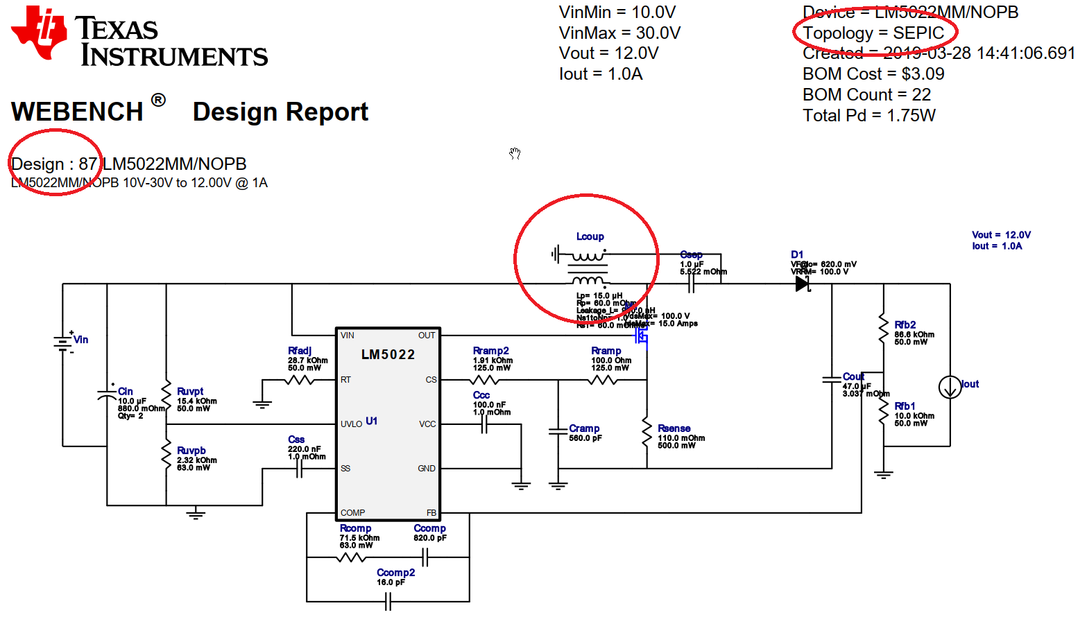
I've already built and tested SEPIC converter based on LM5022 (webench.ti.com/.../webench5.cgi
SEPIC_None&topology=SEPIC&optFactor=3&VinMin=10&VinMax=30&O1I=1&O1V=12&op_TA=30&application=
SWITCHER&origin=ti_panel) and I'm wonder if it is possible to simply modify it to meet above requirements.

  • Hello,

    Thank you for considering the LM5022. Somehow your link of the webench is broken and I cannot open it.

    Do you mean you want to modify the webench design to adjust the output voltage? You can achieve it by adjusting the FB pin voltage to adjust the output voltage. Feed your DAC to the FB pin through a resistor, and you need to choose all three resistors (the two regular resistor as feedback divider), and this third one feeding the DAC output, such that the DAC voltage range can set your output voltage from 3 to 24V.

    Note that using FB you have to use inverse logic, namely higher DAC voltage sets your converter output voltage lower.

    Thanks,
    Youhao Xi, Applications Engineering
  • Hello,

    Thanks for answer. I have no idea why previous link is not working, I hope that this one will work for you: webench.ti.com/.../87

    I have requirement to deliver 12W on output so for 12V there should be 1A but for 3V current should be 4A. Do you think that it is sufficient just to add DAC with resistor between Rfb resistors and output power will be more or less the same for different output voltage?

    Could you please help me with Rfb resistors calculation and DAC selecting with assumption that 12V on output is default value (and should be set after DAC reset)?

    Many thanks in advance for your help.

    Regards,
    Tadeusz

  • Hello,

    Your webench design is just a boost, not a sepic. Refer to the following ref design:

    http://www.ti.com/tool/pmp7305

    The following calculation refers to this ref design. Assume you have a DAC output feeding the FB pin via s resistor Rdac. The original feedback resistor divider is R9 and R10. Then, R9, R10 and Rdac should satisfy the following equations:

    (1) DAC output =0V, Vout=12V :

    (12V/R9) /[ (1/R9) +(1/R10) + (1/Rdac) ] = 1.25V

    (2) DAC output max Vdac, Vout=3.3V:

    [(3V/R9 + (Vdac/Rdac) ] /[ (1/R9) +(1/R10) + (1/Rdac) ] = 1.25V

    (3) Choose R9 the same as the original: 20k, then solve the above two equations for Rdac and R10.

    Hope this clarifies.

    Thanks,
    Youhao
  • Hello Youhao,

    Many thanks for equations.

    Are you sure that my design is boost and not sepic? To be honest there is no significant difference between http://www.ti.com/tool/pmp7305 and my design https:/webench.ti.com/power-designer/switching-regulator/customize/87 (TI displays on design page that it is Topology: SEPIC)

    How about power on output when I change voltage to 3V? Should I expect to have 4A without any additional modification? How about inductor current saturation in this case?

    Regards,

    Tadeusz

  • Hi Tadeuz,

    Sepic requires two inductors, either couple or uncoupled. Boost requires a single inductor.

    If you look carefully, the pmp7305 uses coupled inductors, and your webench circuit uses single inductor. The are completely two different circuit.

    In your application, you need a sepic. Please refer to a power electronics textbook for detailed descriptions. You should start your design with the max current, then when you raise voltage the working current can be smaller and your inductor selection should be okay.

    Thanks,
    Youhao
  • Hello Youhao,

    I have no idea why you can see only single inductor on my design number 87. Please have a look at the attached picture of this design. I can see coupled inductors there and WEBENCH also reports this design as sepic:

    Nevertheless, many thanks for equations and all clarifications.

    Regards,

    Tadeusz

  • Hi
    The responsible engineer is out now. We will reply by 4/12
    Regards,
    EL
  • HI Tadeusz,

    I just came back from a business trip. Sorry for the delay. Somehow I did see a different circuit last time, but the link is no longer accessible.

    The circuit that you showed looks fine. Just make sure that your inductor can support 4A load when you adjust the output to 3V.

    Thanks,
    Youhao