This thread has been locked.

If you have a related question, please click the "Ask a related question" button in the top right corner. The newly created question will be automatically linked to this question.

TPS62740: TPS62740, TPS62737

Part Number: TPS62740
Other Parts Discussed in Thread: TPS62737, , TPS61098, TPS61099, TPS62743, TPS62808, TPS62840

Hi,

I am currently working on a battery operated device having below requirements,

Requirements:

Battery voltage range:              2 V to 3.7V

Output Current during active:  150mA (max)  (pulse current with max amplitute of 150mA for a duration of 15ms)

Output current during sleep:    10uA

Quiescent current :                   in terms of nA (less than 1uA)

Current Status:

I have started developing my design considering TPS62737 initially, it is found to operate as per my requirements, but TI says not to consider it for further designs, 

i want to go for other similar converter with similar specs,

I have also started to work on TPS62740 but then i realized that it cant support 150mA under below condition,

Iout = 100mA max when

VOUTnom ≤ VIN ≤ VOUTnom +0.7V (battery voltage is typ 3.7V)

This means it will usually fall under this condition.

Can you please help me find a better converter which can fit into my requirements?

Thanks,

Manmohan M

  • Hi Manmohan,

    What output voltage do you need? What operating ambient temperature do you need?
  • Hi,

    Operating voltage: 3.3V
    Ambient temperature: 30 deg typ
    Operating temp range: -10 to +60 deg
  • Do you have 1 or 2 cells in series? The 3.3Vout is between your min and max Vin from your initial post.

    Usually, a buck-boost converter would be used here to obtain a regulated 3.3Vout. For your case, can your load accept a lower (or higher) voltage than 3.3V?
  • Hi,

    I am currently using a single battery with below specs,

    Nominal voltage:   3.7 V ,

    Capacity:               2600 mAh 

    Yes, it is best suited to have a buck-boost converter which enables me to use the battery even when the battery voltage goes below 3.3V

    The load operates between 2.8 to 3.3 V

  • Thanks for explaining. If I may summarize your requirement:
    3.7V battery, with a voltage range of 2V to 3.7V
    2.8V to 3.3Vout
    150 mA peak current
    ultra-low Iq needed

    Is that correct? Is there another rail, such as 1.8V, that is needed in your system?

    Let me share this thread with our boost and buck-boost engineers. I don't believe that you can have the lowest Iq with a buck-boost, but it would be a 1 chip solution.

    The other options that I can see would be using the TPS62740 to buck (to 1.8Vout, for example) and then using the TPS61098 or TPS61099 to boost back up to your ~3V.
  • Hi,

    Yes, the requirement is correct.
    But there is no load requirement with 1.8V. All of my load operates at 2.8v to 3.3v

    I do not want to have multiple ICs working in tandom as it increases my BOM cost and also it increases the current drawn.

    TPS62737 works well with my design the only problem was it is not recommended for further designs and because of it the availability of the IC and its lead time becomes an issue during mass production.

    Thanks
  • Hi Manmohan,

    As Chris said, considering the voltages, a buck-boost converter would be a natural solution. However, we do not have a sub 1 µA Iq device (yet), the best we have at the moment is ~10-20 µA. Depending on the frequency of your pulsed load, it might be more important to look at the efficiency around 150 mA than at the Iq.

    It really helps if you know the discharge profile of your battery, all three converter types might give you similar battery lifetimes, see this app note:
    www.ti.com/.../slvae14.pdf

    You mentioned that the nominal battery voltage is 3.7 V, so I assume this is a Li-ion battery, with Vmax=4.2 V?

    Best regards,
    Milos

  • Hi Manmohan,

    What output voltage did you use with TPS62737?

    I'm not sure how it can work since your 2Vin_min is below your required Vout range. I think that maybe something is not completely clear to me.
  • Hi Chris,

    I got your question , i am ok considering  Vin_min is below your required Vout range because almost 70-80 percent of the battery would be drained by then.

  • Hi Milos,

    I am not worried about the efficiency at 150mA because ,

    Current consumption in a day:
    10uA for nearly 23 hours and 55 mins
    150mA for 5 mins

    Since the device spends most of the time in sleep i am more worried about the quiescent current drawn by the converter rather than the efficiency at 150mA during awake which occurs occasionally.

    Thanks,
    Manmohan
  • Hi,

    I have atttached the primary  battery discharge profile

  • Hi Manmohan,

    Thanks for explaining.

    You are welcome to test the TPS62740/3 (or even the TPS62737) in your application. The Rdson may put you in dropout at lower Vins. The TPS62743 has lower Rdson, if the WCSP package is acceptable.

    The TPS62808 has just 2.3 uA Iq, but the 0.35mm pitch WCSP package is too small for some customers.

    This ultra-low power area is a focus for TI. We have new products fairly regularly. There is one device in particular which I think would be a great fit for your application, and it should be on the web and sampling here in a few weeks. If you can wait that long, great. If not, maybe you do a first board with one of the above devices to start working on your system and switch to this new one on the next PCB spin.
  • Hi Chris,

    Thank you for your inputs,

    As you said i would probably go with other combinations before the part you mentioned is released, there is high probability of me missing the part so can you please update me once it is released ?
  • Hi,

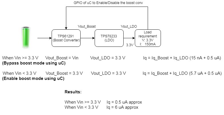
    I have thought of implementing the solution required as shown in the attachment, please correct me if i am wrong,

    Regards,

    Manmohan M

  • That looks good to me, but let me loop in our boost engineer to double check.

    You could also use the 2.8Vout version of the LDO and only boost to 3V. As well, you only need to boost when your output voltage is too low--maybe this is lower than 3V. Both of these should lower the Vin range where you have the low Iq.

    I'll keep an eye on the new device and let you know when it is sampling.
  • Hi, 

    Thank you for all your inputs

    Regards,

    Manmohan M

  • I'm glad we could help. I'll close this thread out for now and make a note to let you know when the new device is sampling. I think you'll like it very much.
  • Hi,

    Can you detail the expected behavior between Vin>Vnom+0.7V --> 300mA max and Vin<Vnom+0.7V --> 100mA max ? If I guarantee Vin>Vnom+0.5V for example is it OK to go to 200mA max ?

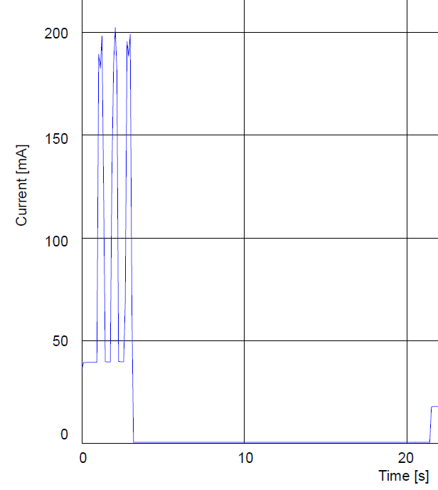
    (I've used TPS62740 @3V from 2xAA 3.6V batteries in // without issue for this kind of load :

    (sorry for post squatting...)


  • Hi Thomas,

    The 0.7V limit is a recommendation, based on how we see most customers using this device. Most customers are powering a radio, which is sensitive to low switching frequencies and the associated higher voltage ripple. To best support this, this IC has a special 100% mode circuit which is explained in section 9.4.2. When Vin is too close to Vout and the load is high, the IC might enter dropout before this 100% mode circuit kicks in. This might create higher ripple and interfere with the radio.

    If you have not seen issues in your application, this is better proof than anything else.
  • Hey Chris, thank you for this quick answer.

    "

    Chris Glaser said:
    When Vin is too close to Vout and the load is high, the IC might enter dropout before this 100% mode circuit kicks in. This might create higher ripple and interfere with the radio.

    This is not enough to engineer :s can you define with number "close" "high" "higher" ? The datasheet is clear : Vin < Vnom+0.7V --> 100mA max but maybe we can use this part in a 100% reliable way with 200mA or 300mA at some conditions. It could extend the applicable field for this part if you define the part behavior more precisely (with worst case data).

    My point is that to me TPS62740 can be the perfect part after the 3.6V lithium primary and the 150mA pulse load of the O.P. is not covered by the datasheet so he discard this part but maybe not for good reason :)

  • This depends on your specific system and the ripple and frequency it can tolerate.

    You can calculate the dropout across the part (and the inductor) from V=IR. The stated 100 mA with 0.7V is the 100% reliable way.
  • Hi Manmohan,

    It took quite a bit longer to finalize the paperwork for our new device.  But is on the web now, with samples and EVMs available.  I hope you like it!

    TPS62840