This thread has been locked.

If you have a related question, please click the "Ask a related question" button in the top right corner. The newly created question will be automatically linked to this question.

BQ24725A: How to turn off the input MOSFET?

Part Number: BQ24725A
Other Parts Discussed in Thread: BQ25895

Hi,

I need to achieve the function:

when adaptor connected, the system is powered only through battery, and draws no current from adaptor.

How can I achieve it?

Can I set the input current register to 0x00 to achieve it?

  • Hi Howard,

    Yes, this should work, and the system will not draw current from the adapter. However, please keep in mind that with the default 10 mΩ sense resistor, setting the input current limit below 128 mA or above 8.064 A will also terminate charging.

    Best regards,
    Angelo
  • Hi,
    we've verified that even by setting input current limit to 0.

    The real current limit is still 128mA.

    When the load is 100mA, Vsys is 9V the same as the adaptor, and the input current is also 100mA.

    This is true both when battery is connected or absent.

    But we want the adaptor to be totally disconnected to VSYS.

    Are there any other way to achieve it?

  • Other questions:
    1. how to know the battery is absent or not?
    2. When battery is absent, what's VSRN like? Will it be kept at the full charge voltage?
    3. When battery is charged to full, when will it restart charge again? Is it true that BQ24725A won't restart charge unless the host MCU told it to start charge again?
  • Hi Howard,

    You could also try setting ACDET to a voltage outside of the valid 2.4 V - 3.15 V range. This will turn off ACFET and RBFET. However, ACDET still needs to be above 0.6 V for SMBus communication and to activate the REGN LDO and various comparators. Please take a look at the description of adapter overvoltage in Section 8.4.2 in the datasheet to see whether that will meet your requirements.

    As for your other questions:

    1) Unlike some other chargers, the BQ24725A doesn't have a BATPRES pin to indicate when a battery is present. However, Section 8.4.5 of the datasheet lists all of the conditions that must be met for charging to begin.

    2) Yes. I tried this on an EVM, and after removing the battery (charged up to 3 V), SRN was regulated to my charge voltage register setting (4.2 V).

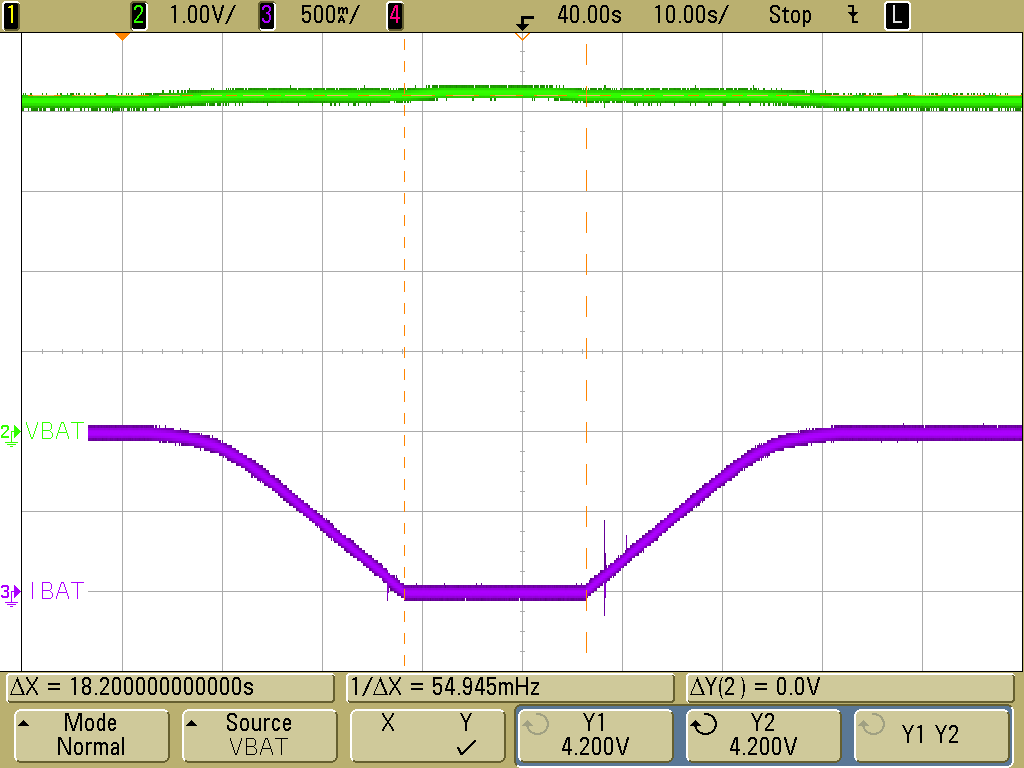
    3) Charging resumes when VBAT falls below the charge voltage register setting. In the waveform below, I increased VBAT from 3.95 V up to 4.25 V, then back down to 3.95 V. You can see that IBAT increases again and charging automatically resumes when VBAT dips below 4.2 V (my charge voltage setting).

    Best regards,

    Angelo

  • Angelo,

    I know there is no dedicated pin or register to indicate the absent of battery. 

    I'm wondering if there is any other workaround.

    For example, BQ25895 doesn't have dedicated register to indicate the absent of battery. But when battery is absent, VBAT will be varying between full charge voltage and recharge threshold in seconds, and the charge status will be varying between "charge termination done" and "fast charging" in seconds.

  • Hi Howard,

    The BQ24725A has only a few registers, so it's difficult to read out the status of the charger. I tried probing every single test point on the EVM, but there's no difference between the floating battery case and the fully charged battery case.

    Here's a solution that might work without adding external circuitry and/or software:

    Step 1: Make sure charging is enabled.

    Step 2: Check the SRN voltage. If it's below your charge voltage register setting, then this indicates that a battery is connected (because if the battery is absent, then SRN will be regulated to your charge voltage register setting). Otherwise, move on to step 3 to distinguish between the fully charged battery case and the battery absent case.

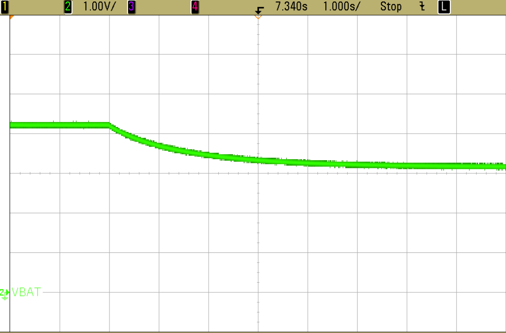
    Step 3: Run a battery LEARN cycle. If the LEARN cycle finishes very quickly and the LEARN Enable bit (ChargeOption() bit [6]) is reset to 0, then the battery is absent, as shown in the waveform below. Otherwise, if the LEARN cycle does not finish very quickly, then a battery is present.

    This workaround operates under the assumption that a real battery will take more than a few seconds to discharge below the battery depletion threshold (ChargeOption() bits [12:11]), but with no battery connected, the LEARN cycle will finish very quickly.

    Another closely related solution would be to follow Steps 1 and 2 as shown above. However, for Step 3, disable charge and see whether the SRN voltage drops quickly. If SRN quickly drops below your charge voltage register setting, then the battery is absent, as shown in the waveform below. On the other hand, if SRN is more or less maintained at the charge voltage register setting, then the battery is present.


    You will definitely need to test these workarounds on your own circuit to see if they will work for you. The amount of time it takes for your LEARN cycle to complete when the battery is absent could vary from my result of <100 ms because of different capacitances in our circuits. Similarly, the amount of time it takes for your SRN pin voltage to decay could also vary from my results.

    Best regards,

    Angelo

  • Angelo,

    thank you very much.

    I have a question about your last waveform, why VBAT doesn't decrease to 0 when battery is absent? If no power source, the voltage on the capacitor should decrease to 0, right?

  • Hi Howard,

    I still had the 19.5 V adapter connected in the waveforms I sent.

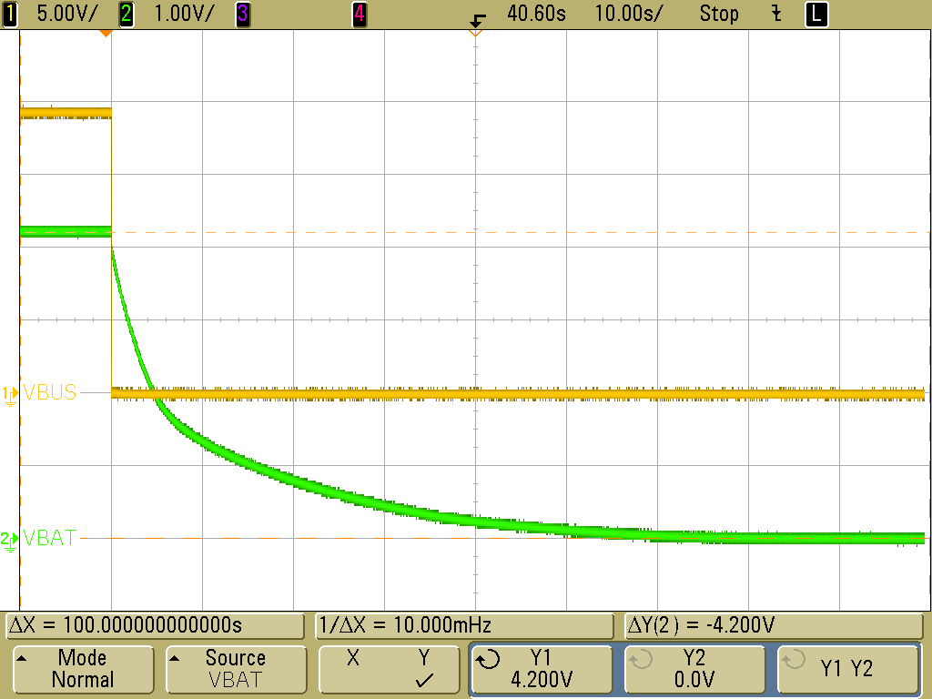
    If neither the adapter nor the battery is present, then you are correct that the voltage on the capacitor will eventually decay to 0, as shown in the waveform below. I disconnected the adapter while charging was enabled, so VBAT decayed from 4.2 V (my charge voltage register setting) down to 0.

    Best regards,

    Angelo

  • Angelo,
    you said: "for Step 3, disable charge and see whether the SRN voltage drops quickly. If SRN quickly drops below your charge voltage register setting, then the battery is absent, as shown in the waveform below. "
    So the waveform you shown @Apr 5, 2019 11:33 PM is at the instant you disable charge with no battery, right?
    So the waveform should be irrelevant to the adapter since charge is already disabled.
    Besides, how did you disable the charge? I can't find any where in the register to disable the charge through software.
  • Hi Howard,

    In the waveform you asked about, I have the 19.5 V adapter connected, no battery connected, and no system load connected. SRN is initially 4.2 V (my charge voltage register setting), but after I disable charge, the SRN voltage decays to about 3 V.

    My most recent waveform used the same test setup, but instead of disabling charge, I disconnected the adapter. You can see that in this case, SRN eventually decays to zero.

    I disabled charge using the charge inhibit bit (ChargeOption() bit [0]). You can enable/disable charging by toggling that bit.

    Best regards,
    Angelo
  • Angelo,
    thank you.
    So my question is why SRN is still 3V when I disable charge?
    it should decay to 0V, the same as disconnect the adaptor. Because by disabling the charge, there is no power source for the capacitor at SRN.
  • Hi Howard,

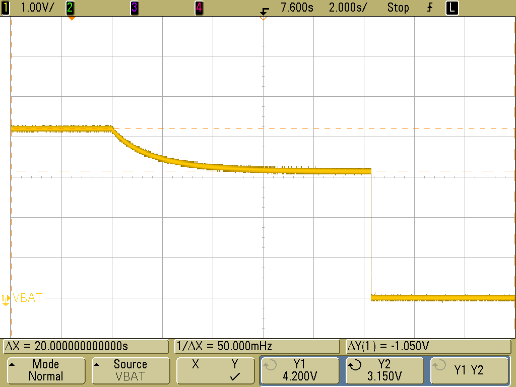
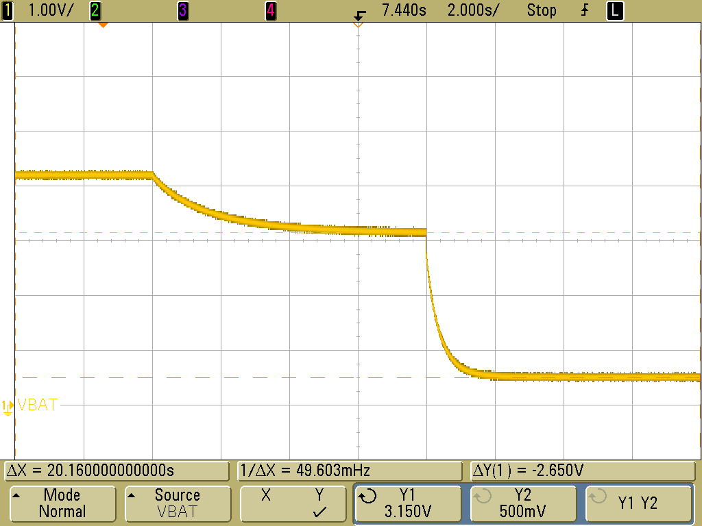
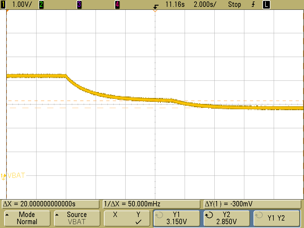
    When charging is disabled, the converter is off. There is also no battery connected, so SRN is a high-impedance node that starts out floating at 4.2 V. In my earlier waveform, the capacitor starts off at 4.2 V and discharges down to around 3.1 V due to small leakage currents.

    However, connecting even a very small load to the BAT pin (10 mA electronic load) causes VBAT to fall to zero very quickly, as shown in the waveform below:

    Even connecting the electronic load without turning it on causes VBAT to fall further below 3.1 V, as shown in the waveform below:

    I even found that just connecting an additional oscilloscope probe also causes VBAT to fall, as shown in the waveform below:

    Therefore, there is nothing on the EVM that regulates SRN to around 3.1 V when the battery is disconnected. Instead, SRN naturally decays due to small leakage currents and stray capacitances in the circuit.

    Considering all of this, it's probably more consistent to use the 1st method I suggested (running a battery LEARN cycle) instead. That method should be less dependent on board specifics while still being able to detect whether or not a battery is connected.

    Best regards,

    Angelo

  • Angelo,

    The customer can't accept the way to make ACDET feel that the adaptor is overvoltage on purpose because it will make the software of MCU confused.

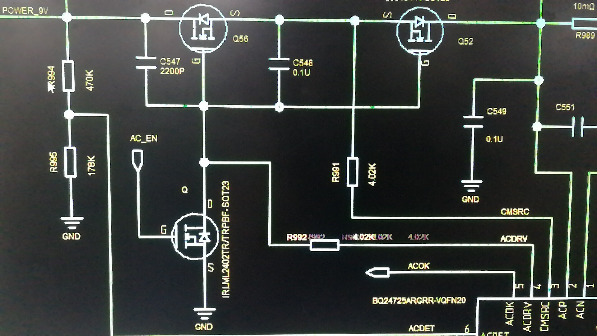
    They tried to pull the gate of ACFET and RBFET to GND with an external MOSFET shown below, AC_EN is connected to a GPIO of MCU. When AC_EN is high, gate side of ACFET and RBFET will be connected to GND and these two MOSFETs will be turned off. But they find that when they set AC_EN low again, the gate side of ACFET and RBFET is still 0, these two MOSFETs can't be turned on again.

    What's wrong with this method?

  • Hi Howard,

    Please see Section 8.4.3 in the datasheet on system power selection. It sounds like this might be related to your issue:

    If the solution involving setting ACDET > 3.15 V won't work for your customer, then another possible workaround is to run LEARN mode, which will turn off ACFET/RBFET and allow the battery to discharge. Other than that, the only other options will probably involve adding external circuitry or more MCU software.

    Best regards,

    Angelo