Hi,
Further to the issue pertaining to making the changes to get a 28V output instead of 24V, i have made few changes in the feedback loop. Below are the changes that are done
1. R32 changed to 4.02K
2. R29 changed to 12K

After making the above changes the circuit outputs 28V but without any load connected to it. But once the rest of the circuit is connected(which consumes 200mA approximately) the 28V output is not constant. Below is the snap shot of the 28V output with and without load
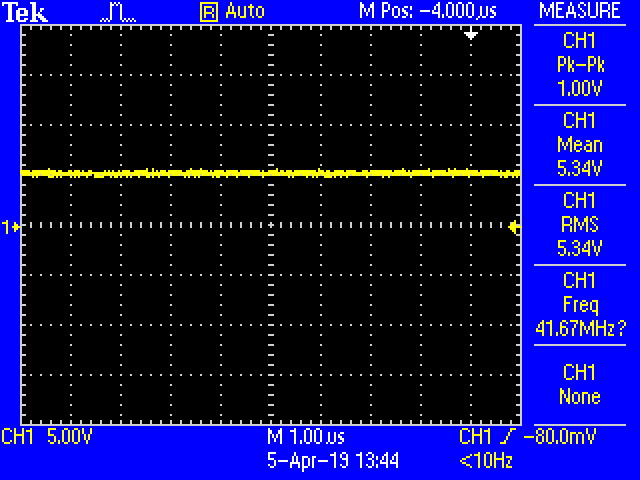
1. Without load

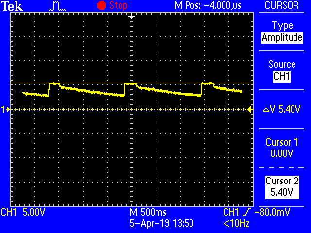
2. With Load

Also the VC voltage changes with and without load as shown below
1. Voltage at VC, without load
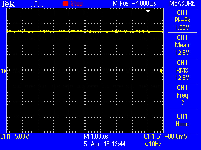 .
.
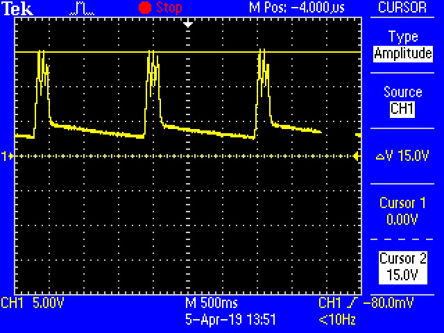
2. Voltage at VC, with load
In case of the designed 24V output, the voltage is constant at 24V in any case. After making the changes in the feedback circuit to get 28V output i am facing the issue and there is no issue if i revert back the changes to get 24V.
Can you kindly suggest if any changes that needs to be done to solve the issue.
Thank you.