This thread has been locked.

If you have a related question, please click the "Ask a related question" button in the top right corner. The newly created question will be automatically linked to this question.

TPS62825: Max output capacitance?

Part Number: TPS62825
Other Parts Discussed in Thread: TINA-TI

Dear *,

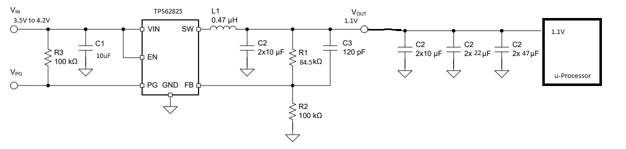
please can someone explain the TI DCS-Controll topology, and what is the max output capacitance?

eg. our rail is 1.1V 1.5A and we have 2x47uF, 2x22uF and 2x10uF on that rail.

Can we use TPS62825 for this rail? Input voltage is from 3.7V to 4.2V .

Br,

David.

  • Hi d_zero,

    First of all, these two application notes explain the DCS control topology (slyt531) and (slyt646). Please read them and I would be happy to assist you if you have further questions.

    Furthermore, I do not really understand your question. TPS62825 can be used for your mentioned specifications. You can use our tool, WEBENCH, and generate designs for your application. 

    I hope this answers your question.

    Best regards,

    Omar

  • Dear Omar,

    in the Datasheet  9.2.2.3 Output filter Design if using 0.47nH inductor then standard output capacitor is 2x 10uF.

    My question is:

    1)

    if i connect additional capacitance ( 2x47uF, 2x22uF and 2x10uF ) that is recommended by the datasheet from u-processor , will this effect the stability of the TPS62825?

    2) Can we change the R2 to 12kOhm and R1 to 10kOhm? if doing so do we also need to change the cff?

    Br.

    D.

  • Dear d_zero,

    Using a lot of additional capacitance might affect the feedback signal and might lead to stability issues. If the reason for these additional capacitors is to ensure voltage stability, then the needed capacitance for this purpose is not that high.

    For the external resistor divider, you can use those values (your Vout will be 1.32V) and you can calculate the recommended value for Cff as showed in page 11 of the DS (1nF)

    Best regards,
    Omar
  • Dear Omar,

    the additional capacitance is specified in the u-processor Datasheet.

    My concern is the effect of this capacitance regarding stability, and that was my question, how can i check, calculate or simulate the TPS62825 regarding stability if loaded with additional capacitance?

    Also i asked in other thread how can i simulate the bode plot of the TPS62825 to check the stability.

    Br,
    David.
  • Hi David,

    You can simulate your circuit on TINA-TI and you can view the bode plots there. I replied to your thread and I advised you to check this video (training.ti.com/tina-titm-waveform-viewer-part-2), where it explains how to generate the bode plots, among other parameters.
    For your specific case, the stability of the TPS62825 should not be affected with the capacitors you mentioned.

    Best regards,
    Omar

  • Hi Omar,

    i exported the schematic from webench in TINA-TI format and opened it in TINA-TI, but when i click Analysis-> AC Analysis -> AC Transfer Characteristic an error appears

    " You must add an input to the schematic"  ??

    I add the TINA-ti file.

    BR,

    D.webench_design_4376384_152.tsc

  • Hi Omar,

    now i replaced the input with voltage generator, and i set the DC voltage to 4V and signal sine wave.

    when i trying to run the simulation i got error: Operating point not found : Component: U1 .D_CURR_LIMIT_D11

    how can i resolve this?

    Best Regards,
    D.
  • Hi David,

    I will assume that you are over the first input issue, since I was able to open your file and run the simulation without problems.
    The error you are seeing means that you have a convergence error. When simulating the transient response, try using the one option of these (Calculate Operating Point - Zero Initial Conditions - Use Initial conditions) that you have not used before. For example if "Use initial conditions" was selected earlier and it gave the convergence error, try with "Calculate Operating Point"

    Regards,
    Omar
  • Hi Omar,

    i'm not doing a transient simulation i'm doing AC analysis to get the bode diagram.

    i can't find the Use initial conditions or calculate operating point in AC analysis?

    I attached new schematic where i get the error.

    First i load the .tsc file and then i go Analysis->AC Analysis->AC Transfer Characteristic -> OK

    Start freq 10Hz

    End freq 2MEG

    number of points 100

    Sweep log

    Diagram: Amplitude & phase

    TPS62825.TSC

    And then i get the error.

    BR.

    David.

  • Omar,

    we need your help on this, can you advise why do we see the error that David reported?

    Thank you
  • David and Bart,

    I apologize about the delay but I still do not have an answer for your question.
    There are two types of Power models created for our products: average models and transient models. Average models are simplified models of the control loop of the device and they are used for AC simulation to provide a Bode Plot. Transient models, on the other hand, are models created for use in time domain simulations and they are not used for AC simulations. The model available for the TPS62825 at the moment is a transient model, which is not suitable for AC simulations. I asked a TINA-TI expert on this matter and I will share the answer once I get it.

    Best regards,
    Omar

  • Hi David,

    So the answer came back and unfortunately an average model for the TPS62825 is not available. Therefore, AC simulations are not possible.

    Best regards,
    Omar