This thread has been locked.

If you have a related question, please click the "Ask a related question" button in the top right corner. The newly created question will be automatically linked to this question.

BQ25895: 4 Layers board review - AGND, GND and Power planes

Part Number: BQ25895
Other Parts Discussed in Thread: TPS61232

Hello,

I'm an embedded systems engineer and i'm actually designing a power supply PCB using BQ25895. I already did some PCB layouts but never as complex as this one, that's why I'm asking for reviews on this forum.

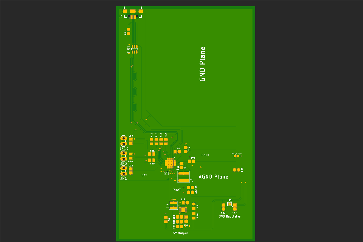
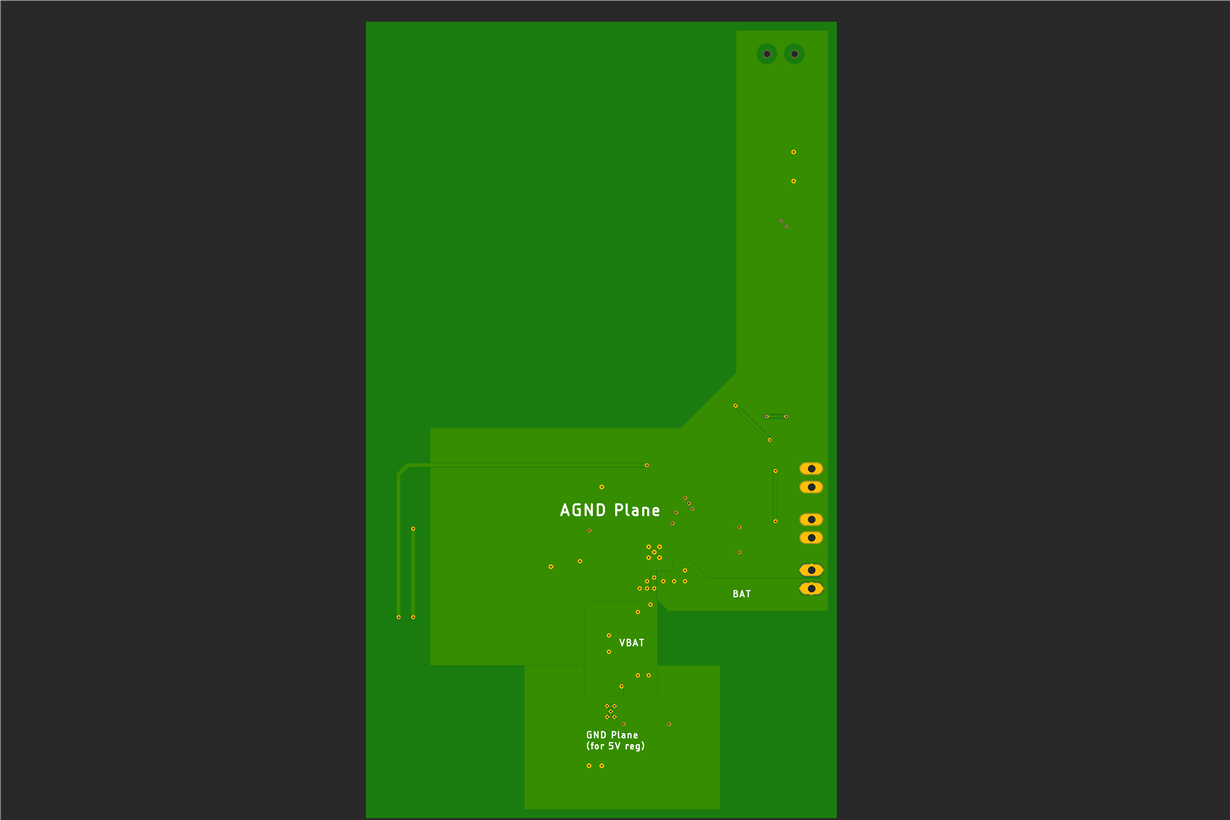
I'm going to soldering it using a reflow oven, that's why there aren't any components on bottom side, I also added some texts on the PCB to help understanding the PCB.

The first big point result as a misunderstanding of the datasheet, I don't know if I should use PMID output or use the switched output (SW, near L4). PMID is only active in "Boost mode", that's why I connected a TPS61232 as a Step-Up converter to the SW output to provide 5V (up to 5A).
To prevent any fails I put a 0 Ohms resistor to get access to PMID plane.

Then, those are the points whom I'm not comfortable:
- Has my PCB enough copper to dissipate the heat and handle current flows ?
- Is my PCB well designed to prevent EMI and ground loops ?

USB has a protection circuit (ECLAMP2122s) to prevent from TVS, ESD and EMI troubles and USB lanes are impedance tuned.

Here, you can find a zip file with:
- Gerber Files
- Capture of TOP and BOT gerber
- PCB Schema

Thank you for reading.

BQ25895_DesignBlock.zip

  • Hi,

    Please check www.ti.com/.../bq25895evm-664 for layout example and visit e2e.ti.com/.../2715274 for some general layout guidelines.

    Thanks,

    Ning.
    Please click "This Resolved my issue" button if this post answer your question.
  • Hi Ning,

    I already followed "Layout Guidelines" section in BQ25895 datasheet's to make this version of the PCB. I also rode the User's guide of the dedicated EvalBoard (EVM-664) to get complementary informations about this IC but it doesn't give me entire confidence to proceed prototyping, especially about temperature and current flows.

    Below, I extracted the 2 capture of my PCB from the Zip file (inner layers are used only for discrete signals, only top and bottom layer here):

    I would like to have dedicated advices to improve my PCB's efficiency (on points I listed on my first message).

    Thank you for your reply,
    regards.

  • Hi,

    Below are some detailed layout guidelines:

    1. Component placement priority:

     1. Cin(VBUS & PMIC) first  > 2. BTST cap > 3. REGN cap > 4. Inductor > 5. Csys > 6. CBAT  > 7. others for signals

    2. Key consideration is to minimize high current path loop.

    3. Route analog ground separately from power ground. Connect analog ground and connect power ground separately. Connect analog ground and power ground together using power pad as the single ground connection point. Or using a 0Ω resistor to tie analog ground to power ground.

    4. Thermal pad needs to follow the datasheet land pattern.

    5. Power ground - Always reserve 2nd layer as power ground

    6. AGND and PGND connection: Connect AGND-PGND with a 0Ω shunt or copper. There is no big current flowing through the joint point. The joint point can be a thermal via or a copper pour underneath the device.

    Based on the guidelines above, the followings are obvious in your specific layout:

    1. Most of the external components are not close to the IC

    2. The IC thermal pad land pattern is different from the d/s suggestion.

    Please double-check the layout per the guidelines provided.

    Thanks,

    Ning

    Please click "This Resolved my issue" button if this post answer your question.

  • Thanks a lot Ning for your detailed answer about how I should improve the efficiency of my layout.

    I'm going to adapt the design and will come back here to click "Resolved" button once I will be sure about of my design (as much as possible, I know that perfect layout doesn't exist).
  • Hi,

    Thank you very much for your understanding. I will close the thread for now.

    Best Regards,

    Ning.
    Please click "This Resolved my issue" button if this post answer your question.