This thread has been locked.

If you have a related question, please click the "Ask a related question" button in the top right corner. The newly created question will be automatically linked to this question.

UCC27714: Vds slew rate different during the deadtime

Part Number: UCC27714

Hi,

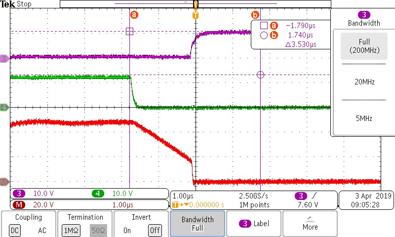
Here is a 3 phase motor driver project using C2000.

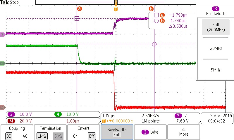
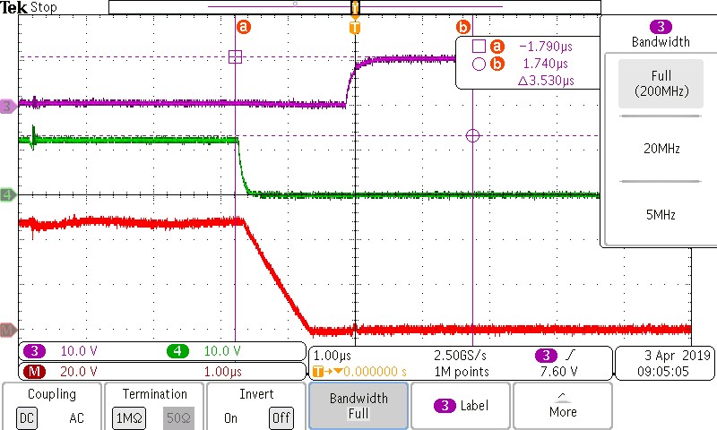
While measure the Vds of High/Low side MOSFET, we found the Vds slew rate are different everytime we measured.
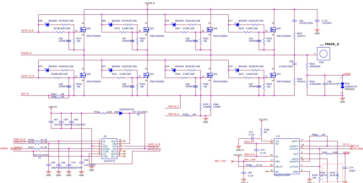
Phase U:

CH3: High side Vgs

CH4: Low side Vgs

  M  : high side Vds


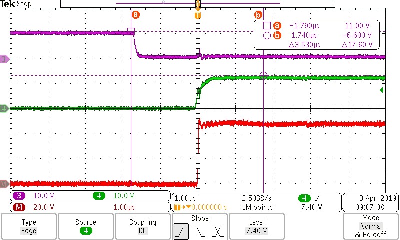
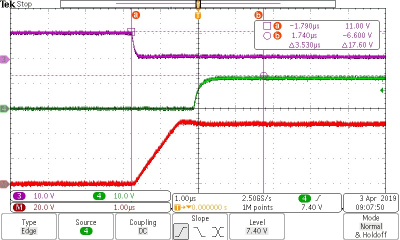
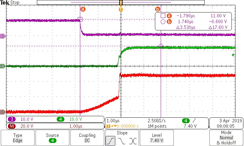
Low side is the same situation.

What makes this happened? Is this a issue?

Thank you.

C.T.

  • Hello CT,
    Thank you for the interest in the UCC27714. The waveforms you show are not a concern, and is an indication of the load operating in different load current ranges. If the peak to peak current is always positive (always above 0) during switching, the waveform in the 1st graph will be observed. When the low side switch is turned off, the current will continue to flow in the body diode of the low side device, until the high side is turned on, this condition will typically result in relatively high dV/dt. The plots 2 and 3 are indicating the current in the switch node is negative at the valley of the ripple. In this case the Vds will transition when the conducting switch is turned off and depending on the dV/dt and dead time can reach zero voltage switching. The dV/dt is dependent on the level of current in the switch node when the switch is turned off.

    These waveforms look normal and very clean, I would not be concerned about the different dV/dt observed.

    Please confirm if this addresses your question, or you can post additional questions on the thread.
    Regards,
    Richard Herring
  • Hi Richard,

    Got it, thanks for your explanation in detail!

    Best Regards,
    C.T.