This thread has been locked.

If you have a related question, please click the "Ask a related question" button in the top right corner. The newly created question will be automatically linked to this question.

LP5569: Breathing Effect

Part Number: LP5569

How can I achieve breathing effect using LP5569? Is it necessary to use to programming engines? If yes how can I program them and if not then what is the other way.

  • Hi,

    It's easy if you use the engine.

    Please refer to the following application report.
    www.ti.com/.../snva822.pdf
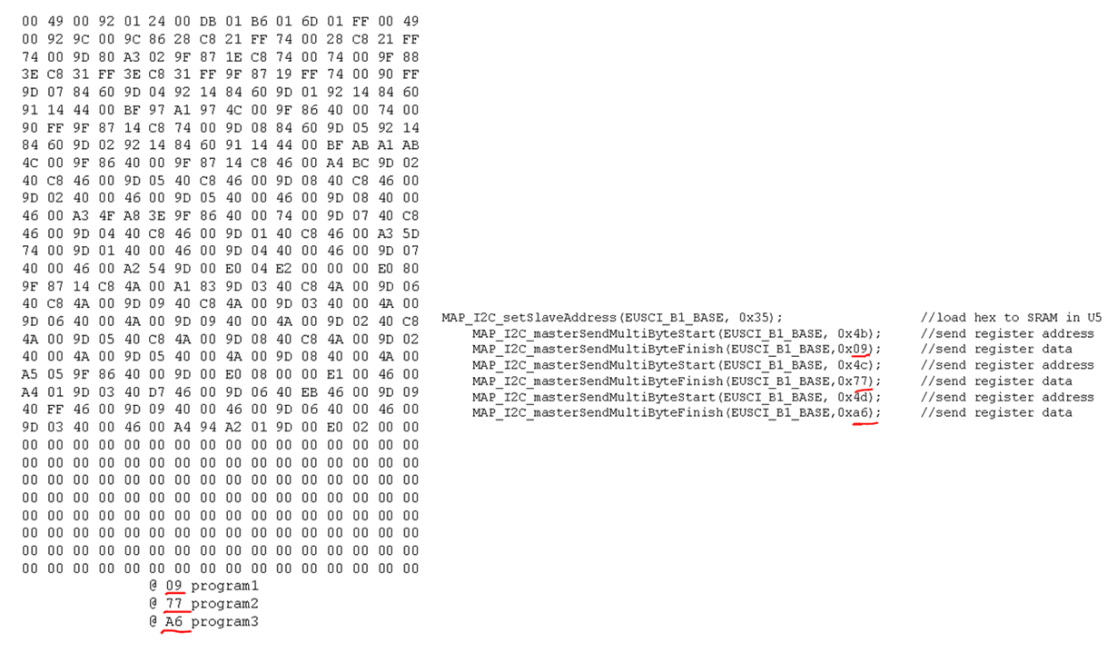
  • I have confusion about the highlighted numbers. From where 0x09,0x78,0xa8 came from?

    Why the loop is from 0 to 16? Why i+j*32 is used?

  • 0x09, 0x78, 0xa8 are the ENGINE1/2/3_PROG_START Register.

    You can find these data from the .hex file.

    The for loop is used to shift the 32*16 bytes data array to the chip SRAM through i2c.

  • Ok I got it. But now I am facing another issue.  My writes are not properly going to SRAM. When I write to page 0 on addresses 5a,5c,5e,60,62,64,66,63 any value and when I read back from these addresses I always get 00. Other addresses are giving right values. but something is wrong with these addresses. I also tried writing 00 to whole memory and reading back I get all zeros. which means that my writes are getting to the memory. I have attached the file in which I have written the data gathered from logic analyzer. First column is for random values written on page 0 of memory and 2nd column show writing 00 to page 0. I have highlighted these addresses with red. Please have a look at code also.

    untitled.pdf

    uint8_t load_sram()
    {
    
    	send_buffer[0] = 0x02;
    	send_buffer[1] = 0x00;
    	send_size = 2;
    	if(FAIL == 	led_driver_send())
    		return 0;
    	hal_gpt_delay_ms(2);
    	
    	send_size = 1;
    	recv_size = 1;
    	led_driver_recv();
    	send_buffer[0] = 0x02;
    	send_buffer[1] = 0x54;
    	send_size = 2;
    	if(FAIL == 	led_driver_send())
    		return 0;
    	hal_gpt_delay_ms(2);
    	
    	send_size = 1;
    	recv_size = 1;
    	led_driver_recv();
    	send_buffer[0] = 0x3C;
    	led_driver_recv();
    	send_buffer[0] = 0x4B;
    	send_buffer[1] = 0x09;
    	send_size = 2;
    	if(FAIL == 	led_driver_send())
    		return 0;
    	
    	send_buffer[0] = 0x4C;
    	send_buffer[1] = 0x22;
    	send_size = 2;
    	if(FAIL == 	led_driver_send())
    		return 0;
    	
    	send_buffer[0] = 0x4D;
    	send_buffer[1] = 0x7D;
    	send_size = 2;
    	if(FAIL == 	led_driver_send())
    		return 0;
    	
    	for(uint8_t j = 0; j<16 ; j++)
    	{
    		send_size = 2;
    		send_buffer[0] = 0x4F;
    		send_buffer[1] = j;
    			if(FAIL == 	led_driver_send())
    		return 0;
    		uint8_t add = 0x50;
    		for(uint8_t i = 0 ; i<32 ; i++)
    		{
    			send_size = 2;
    			send_buffer[0] = add;
    			send_buffer[1] = table[i+(j*32)];
    			
    			if(FAIL == 	led_driver_send())
    			return 0;
    			hal_gpt_delay_ms(10);
    			send_buffer[0] = 0x3C;
    			send_size = 1;
    			recv_size = 1;
    			//led_driver_recv();
    			send_buffer[0] = add;
    			send_size = 1;
    			recv_size = 1;
    			led_driver_recv();
    			if(receive_buffer[0] != table[i+(j*32)])
    			//return 0;
    			hal_gpt_delay_ms(10);
    			add = add + 1;
    		}
    		
    	}
    	
    	send_buffer[0] = 0x70;
    	send_size = 1;
    	recv_size = 6;
    	led_driver_recv();
    	send_buffer[0] = 0x02;
    	send_buffer[1] = 0xA8;
    		if(FAIL == 	led_driver_send())
    		return 0;
    	send_buffer[0] = 0x01;
    	send_buffer[1] = 0xA8;
    		if(FAIL == 	led_driver_send())
    		return 0;
    	
    }

  • Did you get the effect on the LEDs?

    Please check if your LED_ENGINE_CONTROL2 Register (Address = 2h) is 00h. If so please use 10h.
  • I am not getting any effect as the writes are not getting to SRAM. Furthermore if you see the above code at the end i am writting 0xa8 to LED_ENGINE_CONTROL Register. But first all the data should properly load in to SRAM and its not happening
  • Can you set MISC(2Fh) to 0x48? I want to make sure Address auto-increment is enabled.

    Please also share your schematic.
  • I have already enabled auto-increment and i'm using internal clock, no charge pump.

  • CONFIG 000 0040
    LED_ENGINE_CONTROL_1 001 0000
    LED_ENGINE_CONTROL_2 002 0000
    LED0_CONTROL 007 0000
    LED1_CONTROL 008 0000
    LED2_CONTROL 009 0000
    LED3_CONTROL 00A 0000
    LED4_CONTROL 00B 0000
    LED5_CONTROL 00C 0000
    LED6_CONTROL 00D 0000
    LED7_CONTROL 00E 0000
    LED8_CONTROL 00F 0000
    LED0_PWM 016 00FF
    LED1_PWM 017 00FF
    LED2_PWM 018 00FF
    LED3_PWM 019 00FF
    LED4_PWM 01A 00FF
    LED5_PWM 01B 00FF
    LED6_PWM 01C 00FF
    LED7_PWM 01D 00FF
    LED8_PWM 01E 00FF
    LED0_CURRENT 022 00AF
    LED1_CURRENT 023 00AF
    LED2_CURRENT 024 00AF
    LED3_CURRENT 025 00AF
    LED4_CURRENT 026 00AF
    LED5_CURRENT 027 00AF
    LED6_CURRENT 028 00AF
    LED7_CURRENT 029 00AF
    LED8_CURRENT 02A 00AF
    CP_CONFIG 02E 0000
    MISC 02F 0050
    MISC2 033 0002
    I2C_GROUP 034 0000
    IO_CONGROL 03D 0002
    ENGINE1_PC 030 0000
    ENGINE2_PC 031 0000
    ENGINE3_PC 032 0000
    ENGINE_STATUS 03C 0080
    VARIABLE_D 03E 0000
    RESET 03F 0000
    ENGINE1_VARIABLE_A 042 0000
    ENGINE2_VARIABLE_A 043 0000
    ENGINE3_VARIABLE_A 044 0000
    MASTER_FADER1 046 0000
    MASTER_FADER2 047 0000
    MASTER_FADER3 048 0000
    MASTER_FADER_PWM 04A 0000
    ENGINE1_PROG_START 04B 0000
    ENGINE2_PROG_START 04C 0000
    ENGINE3_PROG_START 04D 0000
    PROGRAM_MEM_PAGE_SELECT 04F 0000
    PROGRAM_MEM_00 050 0000
    PROGRAM_MEM_01 051 0000
    PROGRAM_MEM_02 052 0000
    PROGRAM_MEM_03 053 0000
    PROGRAM_MEM_04 054 0000
    PROGRAM_MEM_05 055 0000
    PROGRAM_MEM_06 056 0000
    PROGRAM_MEM_07 057 0000
    PROGRAM_MEM_08 058 0000
    PROGRAM_MEM_09 059 0000
    PROGRAM_MEM_10 05A 0000
    PROGRAM_MEM_11 05B 0000
    PROGRAM_MEM_12 05C 0000
    PROGRAM_MEM_13 05D 0000
    PROGRAM_MEM_14 05E 0000
    PROGRAM_MEM_15 05F 0000
    PROGRAM_MEM_16 060 0000
    PROGRAM_MEM_17 061 0000
    PROGRAM_MEM_18 062 0000
    PROGRAM_MEM_19 063 0000
    PROGRAM_MEM_20 064 0000
    PROGRAM_MEM_21 065 0000
    PROGRAM_MEM_22 066 0000
    PROGRAM_MEM_23 067 0000
    PROGRAM_MEM_24 068 0000
    PROGRAM_MEM_25 069 0000
    PROGRAM_MEM_26 06A 0000
    PROGRAM_MEM_27 06B 0000
    PROGRAM_MEM_28 06C 0000
    PROGRAM_MEM_29 06D 0000
    PROGRAM_MEM_30 06E 0000
    PROGRAM_MEM_31 06F 0000
    ENGINE1_MAPPING1 070 0000
    ENGINE1_MAPPING2 071 0000
    ENGINE2_MAPPING1 072 0000
    ENGINE2_MAPPING2 073 0000
    ENGINE3_MAPPING1 074 0000
    ENGINE3_MAPPING2 075 0000
    PWM_CONFIG 080 0004
    LED_FAULT1 081 0000
    LED_FAULT2 082 0000
    GENERAL_FAULT 083 0004
    
    What's your Vin?

    Did you get the LED ON without SRAM? Like the following register setup.

  • Vin = 2.8

    And yes I am able to turn on all the leds without SRAM.