This thread has been locked.

If you have a related question, please click the "Ask a related question" button in the top right corner. The newly created question will be automatically linked to this question.

UCC256301: FEEDBACK COMPONENT VALUES FOR UCC256301

Part Number: UCC256301
Other Parts Discussed in Thread: TPA3255, UCC28C45, UCC2897A, UCC3808-1, TL431

Dear Team

I am beginning to develop an LLC  DC-DC converter using the UCC256301. 
My input voltage is 12v (10-12v)

Output voltage will be 53v  as I'm intending to use this with a TPA3255 audio amplifier in a 'portable' application, so I'm seeking the best possible efficiency.

I realize that I have to alter a number of values/parts to facilitate the 10-12 v DC input operation, but the spec sheet seems to suggest this is possible within the range of input values required for the various functions.

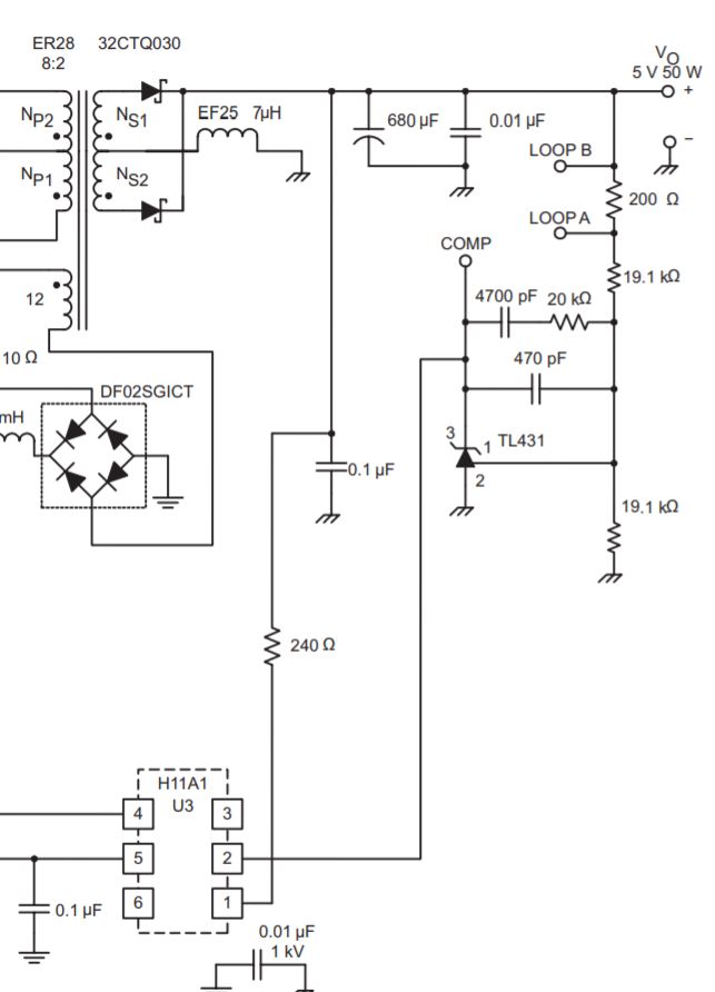
As I look at the suggested application information, I find myself a tad confused on the matter of calculating the feedback resistor values.
In the AC/DC schematic it shows a number of oddly valued resistors that probably only exist in some parallel universe. (See Image)

I don't need isolation in this application due to the low voltages involved.  

QUESTIONS.
Is there a simple alternative cct which does not require the use of the OPTO coupler and the TLV reg  (as per image) ?
I obtained the feedback arrangement directly from the EVM schematic, but that has 12v o/p and I have 53v.

If this is feasible, can I get some assistance with such a feedback arrangement and some values ?

Web Bench will not allow <30v DC input so I can't resort to that for design help.

Thanks

Julian de Ross

  • Julian

    We do not recommend using UCC256301 for input voltage that's 10-12V. The resonant LLC topology works well when the input voltage is much higher, such as 400V. The voltages and control law timing are not designed for such low input voltage so it will not work well.

    if you need high efficiency in this power range we recommend using an active clamp forward with UCC2897A or a flyback with UCC28C45. UCC2897A needs an external E/A signal that goes to the FB pin. UCC28C45 has an internal E/A so you can use typical type 2 or 3 compensation with the integrated op amp on FB and COMP pins.

    Best Regards,
    Eric
  • Hi Eric

    thanks for taking the time and making the effort to help me.

    The UCC2897A seems to provide at best 93% efficiency which is within the kind of range I'm seeking. (as the product is a battery powered portable PA system) but I note it suggests a minimum Vin of 36v.

    Pity I've already done a PCB for the 256301... When you say "will not work well" can you flesh that out a bit? Do you mean unstable, inefficient, blows up... difficult to compensate/stabilise ?

    Even if this part is not useful for my DC DC converter, I do have another board which is part of the product.. an AC-DC converter which takes full mains voltage.

    Perhaps for the DC-DC low voltage unit I'm better off looking at a pure PUSH PULL approach? If you feel this might give me good efficiency, can you recommend a TI part which will do that job?
    I've had a look at a Micrel part..MIC3808 which looks pretty good, but I prefer to remain part of the TI family.

    Over to you Eric.

    with thanks

    Julian

  • Hi  Eric

    I've been doing some thinking about alternative approaches and have come across a likely prospect in the form of the UCC3808 which is a TI part.

    Push Pull.. should work at low voltage... the only difficulty I find is the lack of information about calculating the feedback resistor/capacitor values.

    In the image attached, the circuit uses the 3808 to product 5v output.  I need 53v.

    To save me nagging you folks, is there a document somewhere which lays out the method of determining the values of those parts in the secondary feedback/compensation cct?  Failing that, can you assist me to work out what should work for a 53v output?

    Regards

    Julian

  • Julian

    What I meant when I said that resonant LLC will not work well here is that the topology is not well suited for your operating parameters. Resonant LLC achieves high efficiency by achieving zero voltage switching on the input FETs by creating a resonant current. When the input voltage is very high, such as 400V, this operation enables very good efficiency. When the input voltage 10-12V the advantages of ZVS are drastically reduced, so the performance will be worse than other topologies since there is still a resonant current that creates additional losses. We have not tested UCC256301 with such a low input due to these system level issues so I can't definitively say if it can work or not, but this device was designed for a much higher input so there will be many issues getting it to work at this range.

    Below are some papers that go into more detail about resonant LLC
    www.ti.com/.../slup263.pdf
    www.ti.com/.../slup306.pdf

    The "best" topology is subjective to what the top concerns are for the design, which is what you will need to determine. What we can help with at TI is provide information to understand the trade off for each topology so you can make an informed decision.

    I recommend you watch this video on different DC/DC topologies to help understand the pro/con for each one training.ti.com/selecting-optimal-topology
    I also recommend you use our Power Stage Designer tool to put in your operating parameters so you can see what voltage and current stresses various devices in your supply will have. This will help you estimate what the cost and performance of your power supply will be www.ti.com/.../POWERSTAGE-DESIGNER

    UCC3808-1 is a good push-pull controller. The feedback compensation used in this design is a typical TL431/opto based design.
    The following app note goes into the fundamentals of how to design for a compensator like this. The TL431 acts as a combined op amp and Vref at 2.5V www.ti.com/.../slva662.pdf

    Best Regards,
    Eric