This thread has been locked.

If you have a related question, please click the "Ask a related question" button in the top right corner. The newly created question will be automatically linked to this question.

UCC28070: Current spikes to limit on 10% load

Part Number: UCC28070

Hi,

I am designing 3kW PFC based on UCC28070, and I am getting weird problems with current regulator.

I have connected resistive load for 350w output power and started slowly increase voltage on regulating transformer but when IC starts operating current is jumping all over the place. When I reduce voltage to 70V it will start work kinda normal without current spikes.

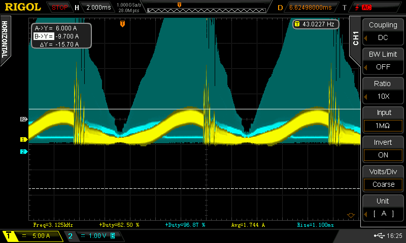
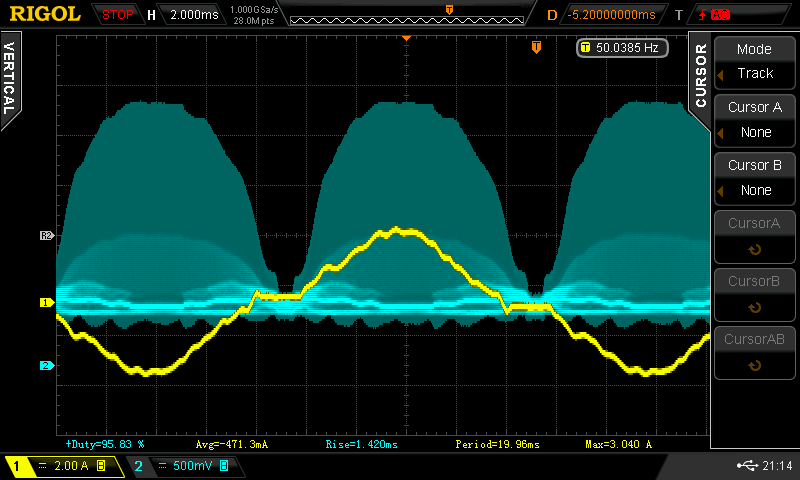
I enclosed current waveforms from La and sensed current on CSA pin. What could cause such a problem? Should i measure other waveforms? 

Also added exel sheet with used parameters.

Thanks, in advance!

  • Hello kovama1,
    I notice three issues :
    (1) The UCC28070 has a minimum switching frequency of 30kHz and you are running it at 10kHz
    You should use the UCC28070A which has a minimum switching frequency of 10kHz
    (2) The calculator is recommending a minimum inductance of 830uH and you have chosen to use 250uH.
    This will result in severe discontinuous conduction.
    You should either use the recommended inductance or increase the switching frequency.
    (3) The reset resistor on the CT is too high and may cause saturation of the transformer.

    Some values in the calculator are negative because you entered zero dither and some compensation components are not as recommended but that should not cause the gross loss of control that you are experiencing.
    Please make the recommended corrections and your power supply should behave better.

    Regards
    John
  • Hello John,

    (1) The 10kHz switching frequency was mistake I actualy used 75k ohm Rt resistor so I am running on 100kHz.

    (2) This was fixed with change in frequency now its corretly 83uH so my 250uH coils should be fine.

    (3) I have changed my reset resistor to 200 ohm and reset capacitor to 43pF.

    I measured current through coil A and voltage on IMO pin. It seems like current drops with no obvious reason and then regulator tries to compensate that and that create current pulses.

    Maybye i shoud cange  components on CAOA and CAOB pin since theese are not exactly same as calculated from exel sheet.

    UCC28070 Design Tool _RevA (3kw pfc_fixed frequency).xls

    Thanks for your reply

  • Hello kovama1,
    It looks like the current is getting very high during these spikes.
    Try reducing the DMAX value. It may be that the CT is saturating because the off time is not sufficient to rest the core.
    If you reduce the time base what does CSA,CSB look like during these events.

    Regards
    John
  • Hi John,

    I have also changed compensating values more corretly to exel sheet. 

    Actualy selected are there:

    UCC28070 Design Tool _RevA (3kw pfc_fixed frequency + values + max duty).xls

    I have also reduced duty to max 80%. Then I did test but behavior is still same (mabye too big reset capacitor?). Should I use demagnetizing circuit with zener and diode istead? Current tranformer used: Wurth Electronics 750316796


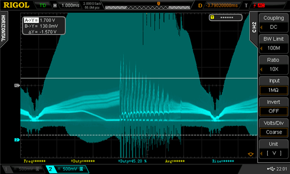
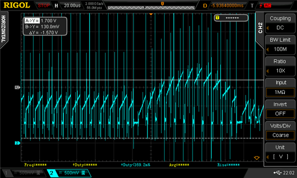
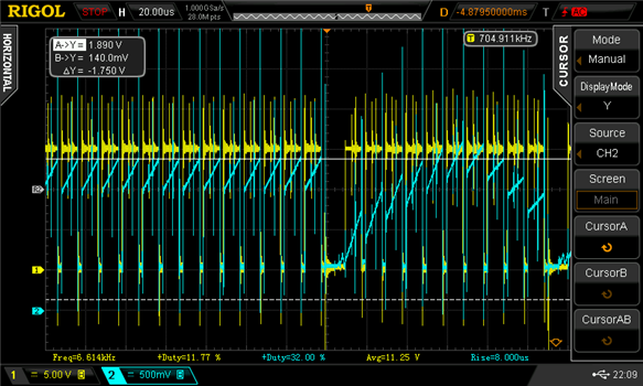
    Measured CSA and CSB waveforms: (CSB measured simutaneusly with yelow GDB signal)

    Thanks for your reply ;)

  • Please post the schematic , BOM and pcb layout files and I will review the documents
    Regards
    John
  • Hi John,

    It took some time, but I prepared requested files for you.

    My PFC design is created from 3 separate boards. UCC28070 module, mosfet driver and power board.

    Its desinged to be able to run also on three pahses with non ideal power factor, but for now I am trying to get it to work on one phase ;)

    Faults in schematics that was found and resolved:

    In UCC28070 module is missing capacitor on VREF => added

    In UCC28070 module in board design is unconnected ground for C4 => fixed with wire connection

    In power board for PWM Ramp and Offset Circuit the VCC and GND signal for cap and resistor is mismatched=> repaired with wires on board


    Thanks for checking my design

    Driver.zip

    PFC_ new values.zip

    UCC28070_new values.zip

  • Hi John,

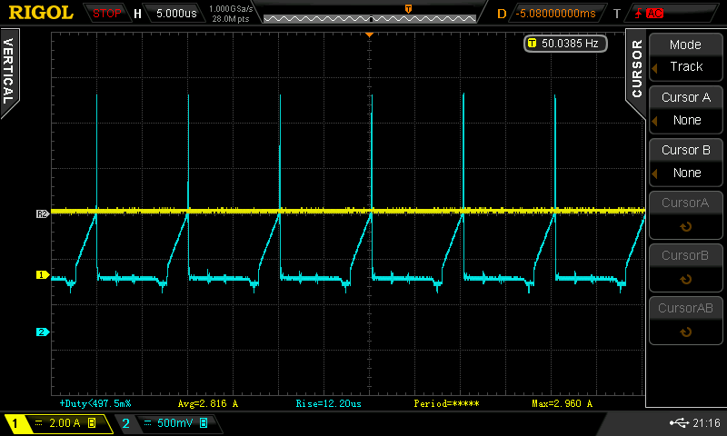
    I did some testing today. I tried to add more input voltage (300V/AC), and current spikes are lower. But overall its still unstable.

    I found that channel B act weird. It looks like every 4th impulse is missing.

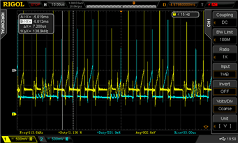
    There are measured CSA(yellow) and CSB(blue) pins simultaneously:

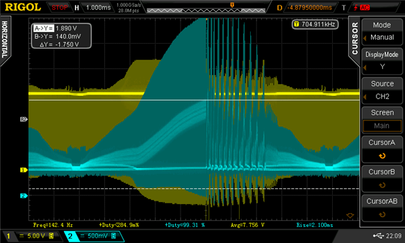
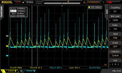
    Then I measured pin CSB and current trough coil B with probe:

    It looks like with more voltage current still make its silly things but at higher frequency so it will not rise to current limit.

    Hope this could help somehow

    Martin

  • Hi John,

    I changed values of filtering capacitors on VSENSE and IAC and circuit started to work quite better.

    Next week I will try to add more load and hopefully it will work normally.

    Regards

    Martin

  • Hi Martin,
    These waveforms are much better and I can see that you are on the correct path.
    Please open a new post if we can provide further help.
    Regards
    John