I am working to integrate part BQ25890 as part of a student project. The device manages a single 18650 and powers a device requiring 5A continuous current. I have followed TI's reference design and layout guidelines and upon testing the board under load have experienced some problems. After drawing 4.5A for about 10 seconds the device shuts off, I believe due to thermal shutdown but I am not positive as I only had a handful of times to test. After testing this behavior a few times the device now shuts off instantly when any significant power is drawn (>500mA). The resistance between BAT and SYS is now 75 ohms. There are no faults reported and I can still communicate via I2C.
I've followed TI's reference design from the datasheet and have included PDFs of my layout and schematic. Please let me know if you see any issues or if I just need to heatsink the chip more carefully. I am certain that the rest of the board can handle the current, as I have tested the device under load simply supplying voltage to the SYS pins and there are no thermal issues. From my calculations my 5A load should produce about 0.5W of heat, according to an Rgs(BATFET) of 19mOhm.
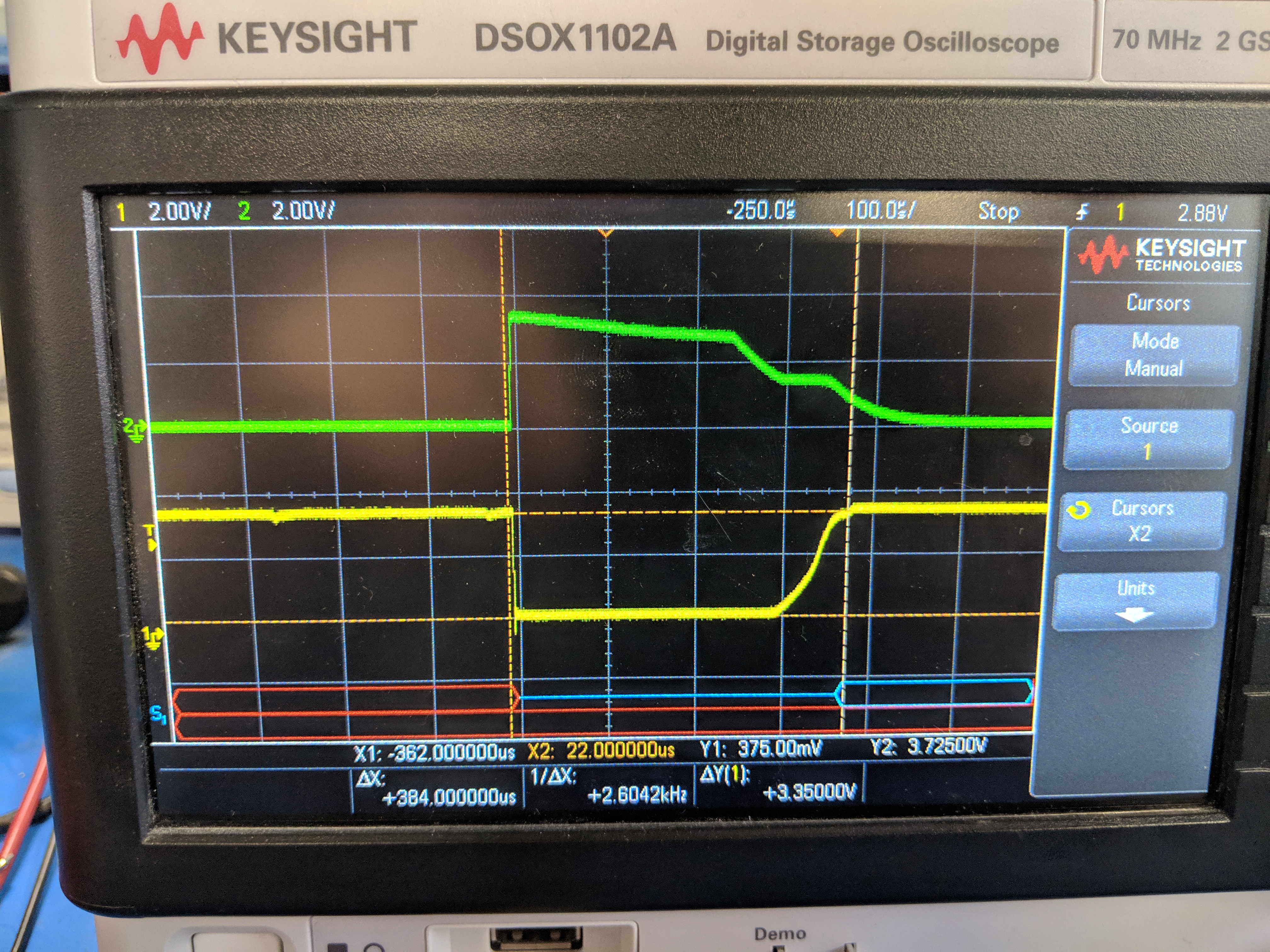
The physical board is 1oz copper with 2 layers. I am certain there are no shorts or mechanical issues with the board and was careful during the reflow process to rework anything wrong with the board before powering it. It works perfectly fine just powering the microcontroller and OLED, only when I apply load does the SYS voltage drop. I have also attached pictures of the behavior on my scope - the green channel is voltage to the gate of the MOSFET controlling the load and the yellow channel is SYS voltage. You can see that the device very quickly responds to the load and SYS voltage recovers when the MOSFET shuts off.
Thank you kindly.