This thread has been locked.

If you have a related question, please click the "Ask a related question" button in the top right corner. The newly created question will be automatically linked to this question.

TPS65218: PWR_EN question

Part Number: TPS65218
Other Parts Discussed in Thread: AM4378, ,

we designed a custom board using the am4378. we attempted to connect in the PMIC for that chip OR several LDO's for power options (either or, not AND)

when we use just the PMIC we had issues with power starting up and then being turned off ~17ms later. this wasn't all the time, mind you. it was something like 50% of the time. the rest of the time it started up and stayed up

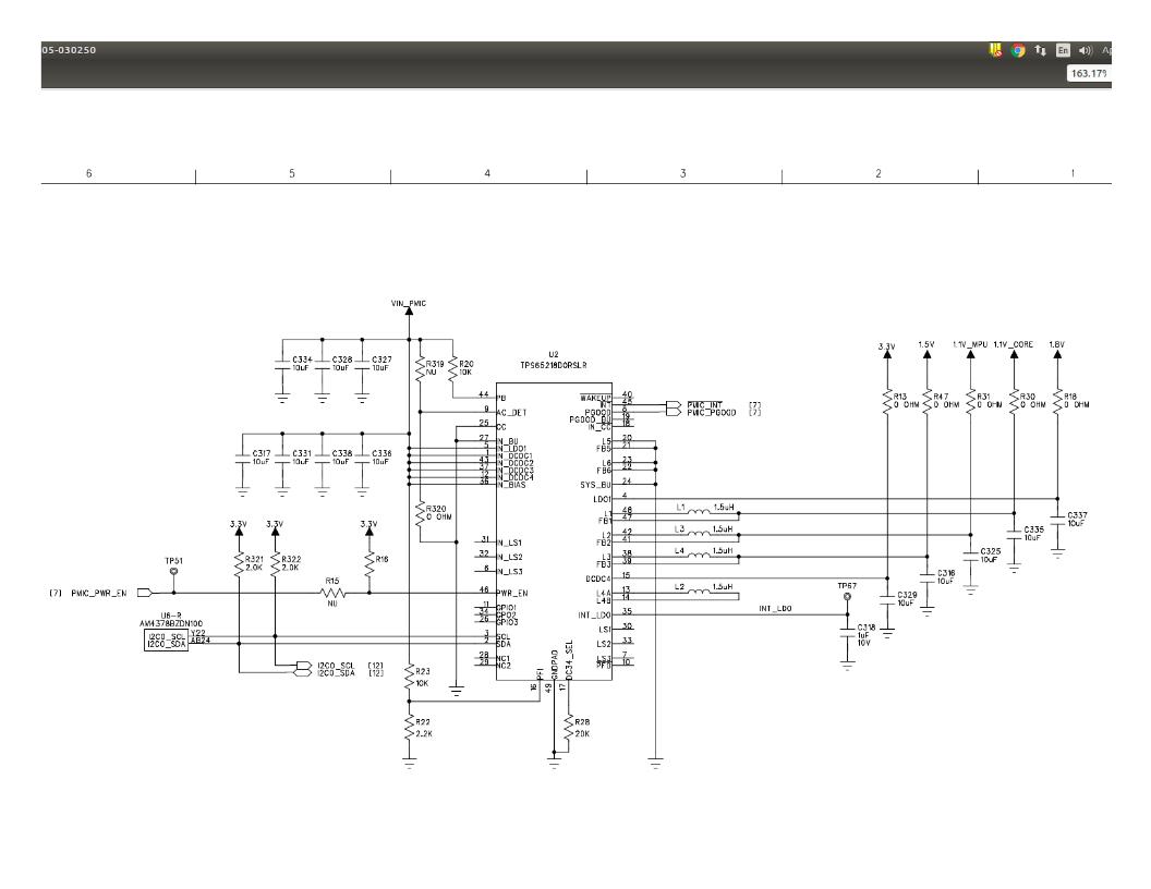
on our custom board we opted to not use the RTC and so the RTC_PMIC_EN is not connected to PWR_EN. our board connected PWR_EN to 3.3V with a pull up which we didn't think was an issue because according to the datasheet it has a minimum voltage of 1.3 but no maximum. i do see an issue that the RTC_PMIC_EN pin that usually turns on the PMIC is a 1.8V pin, which is the first voltage rail to come up and we hooked it up to 3.3V which is the third rail to come up. according to the datsheet however that shouldn't matter because we have 20s before the power down sequence begins (5.3.1.1) without connecting 3.3V which should come up long before then. when we disconnected the PWR_EN from 3.3V and connect it to the 1.8V rail it seems to power up every time now without issue. does that make sense? if so could you tell me where my interpretation of the datasheet was wrong?attached is the page of the schematic with the PMIC. 

just to add: we changed the PFI resistors to bring it way away from 800mV to rule that out, we verified that Vin_PMIC had no dips (5V), and we verified that the resistors that connected the LDO option to the power rails were really NU

  • Did you try testing with PWR_EN pulled up to VIN_PMIC? The maximum input for this pin is the same as all the IN_xxxx pins, which is recommended as 5.5V

    I do not see any issues connecting PWR_EN to 3.3V, but it is not necessary if you want the PMIC to be enabled anytime power is applied to the system.
    Pulling PWR_EN up to VIN_PMIC is more straightforward.
  • As a side note, I am also concerned that the output capacitance you used on the 3.3V rail is incorrect:
    The recommended output capacitance for DCDC4 is 47uF + 0.1uF, but your schematic shows 10uF.


    Finally, the value of R16 is not listed on your schematic. What is it?
  • i believe R16 is a 10k

    so it would be a mystery on to you as well as to why going from 3.3V to 1.8V would make our PMIC function normally? any other ideas as to what could explain why our PMIC would not power up properly?
  • Yes, it is a mystery. But there could be something that explains it: DCDC4 is working extra hard to power-on with a lot of strong pull-up resistors and possibly a load from elsewhere. Then everything is pulled up and DCDC4 does not need to supply as much current, so it overshoots.

    This is a bit of a stretch, but as you said it is a mysterious phenomena.

    But this much is clear, it has nothing to do with the state of the PWR_EN pin itself. This is caused by a reset due to DCDC4 being above VOV or below VPG.

    The only mystery is why it is dependent on a single resistor, R16. Just for the sake of argument, I would try using 100k for R16 as the datasheet suggests. And you absolutely must use the recommended output capacitance for DCDC4 is 47uF + 0.1uF (your schematic shows 10uF).

    Finally, your schematic says TPS65218D0 but this question says TPS65218 (which means -B1 version). Please confirm you are using the -D0 version.

    Ensuring that DCDC4 is operating correctly is the key to fixing the problem.
  • i will see if trying those changes (R16 is 100k, 47uF for DCDC4)

    it is a D0 part. my bad when making the post. i am unsure what the main difference is as the datasheet doesn't seem to make a very big deal out of the d0 part other than the chip ID register
  • should i make those component changes with PWR_EN connected to 3.3V to see if it works or were those just suggestions for the next build?
  • Sure, you can try making those component changes on your existing board.

    On your next board build, you should pull up PWR_EN to the main 5V supply voltage to the PMIC.

    However, if you still have issues related to DCDC4 after changing the output capacitors, it could be a serious layout issue or a schematic issue that I did not identify. Building a new board without fixing the root cause could lead to further frustration.