This thread has been locked.

If you have a related question, please click the "Ask a related question" button in the top right corner. The newly created question will be automatically linked to this question.

LMR23630: How to calculate the phase and again margin?

Part Number: LMR23630


Following is the circuit of an existing design:

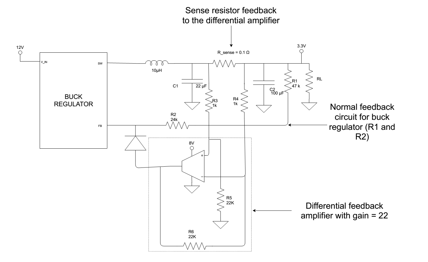
As in normal buck regulators, feedback path is R1 and R2.

Apart from that their is an additional differential voltage feedback path. This path will be active once the voltage across the sense resistor is enough to give the feedback to turn-on the diode.

Could you suggest how to calculate phase and gain margin?

  • Vishnu,

    You have 3 options that I see:
    1. Use classical control theory and some math. This analysis can be done by breaking out a textbook or looking up classical controls online.
    2. Simulate your circuit in a simulator which can do bode plots.
    3. Build the board and test it in the lab.

    -Sam
  • Hi Sam,

    I am interested in the first method. Could you please any reference if TI have one?

    Or is their any similar information or calculation that can be helpful to solve the math?

    Regards

    Vishnu

  • Visnhu,

    SLVAE09A has some good information but you may need more of a purely educational resource. You can search online for classical controls lectures to get a better understanding of control theory. E2E and TI content such as app notes focus more heavily on the implementation of common solutions.

    -Sam