This thread has been locked.

If you have a related question, please click the "Ask a related question" button in the top right corner. The newly created question will be automatically linked to this question.

BQ27Z561EVM-011: PWR LED turns on when battery is connected.

Part Number: BQ27Z561EVM-011

Hi,

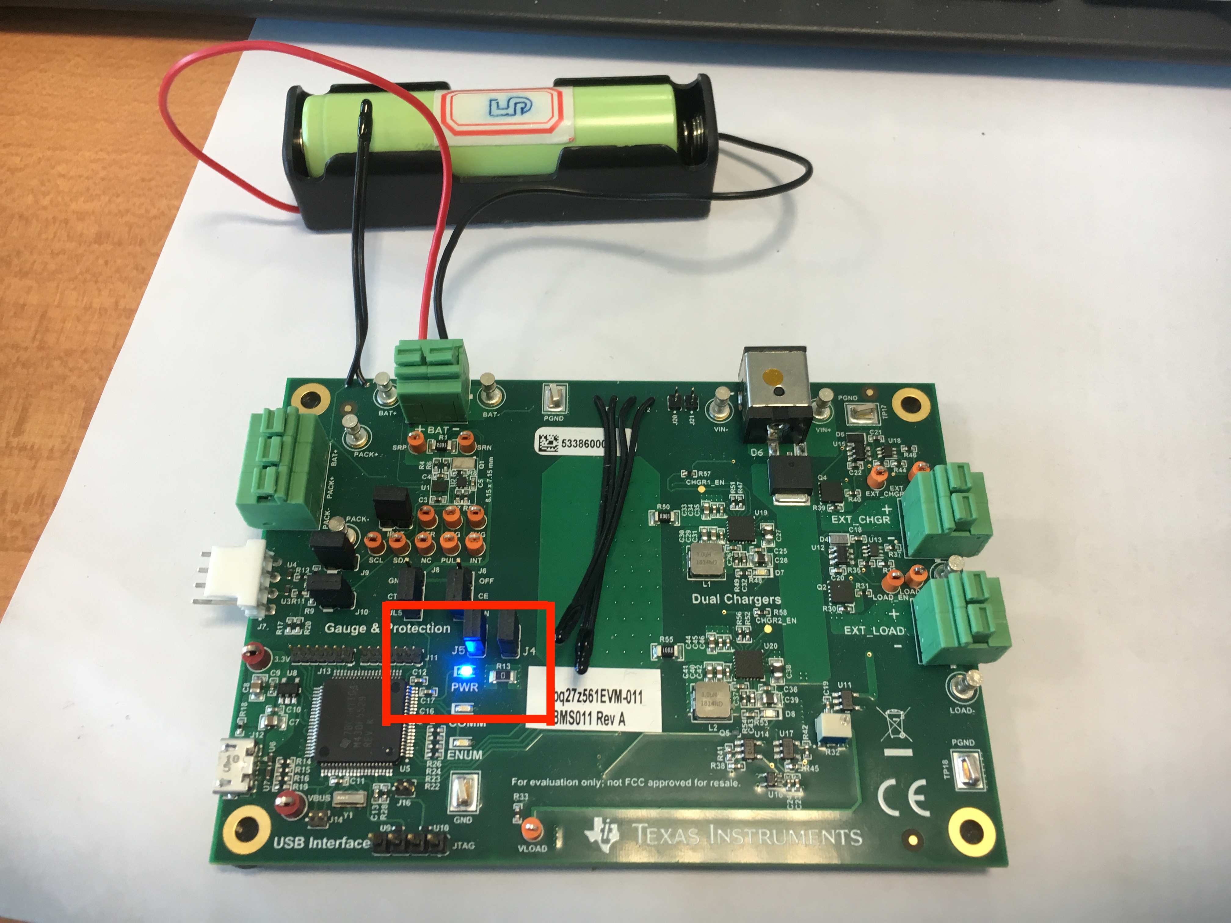
from yesterday, my BQ27Z561EVM-011 doesn't work. It comes out a very wired behavior that when only battery is connected to the EVM, the PWR LED turns on. I have already kept this EVM working for one month. During that time, it work perfectly. But the PWR LED never turns on when only the battery is connected. I check the schematic. There is no information about PWR LED is connected to battery. Anyone could help me find the reason?

Thanks,

Wenlong

The photo of the wired behaviour:

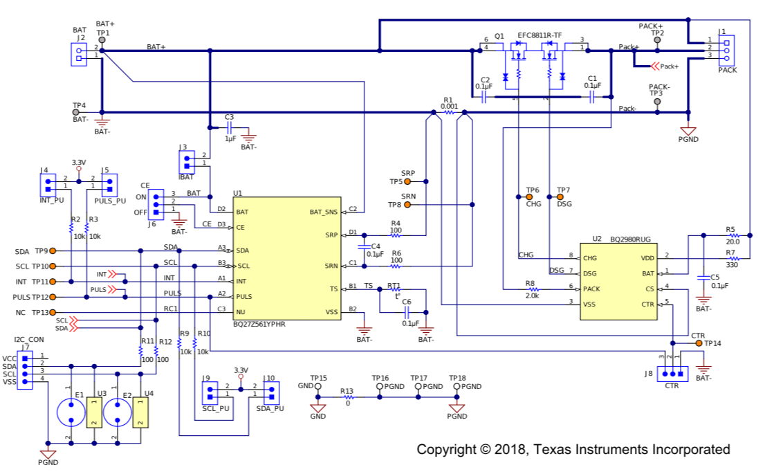
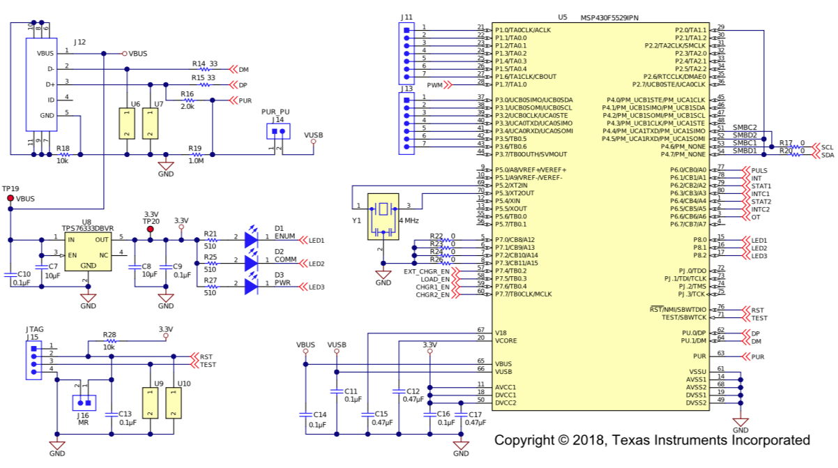
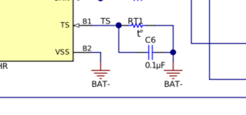
The schematic of BQ27Z561EVM-011:

  • Wenlong,
    I would encourage you not to focus on the power LED but to focus on getting the chip working. In my previous response to your post, i had requested that you placed a scope on the TS pin to ensure that it is pulsing to know if the chip if functioning. I do not believe that LED has anything to do with the functioning of the gauge IC

    thanks
    Onyx
  • Thank you for your reply, Onyx.

    Could you give me some explanation about why there will be pulses on TS pin? From schematic, I see TS is connecting BAT- through the external thermistor as shown below:

    On the datasheet (https://www.ti.com/lit/ds/symlink/bq27z561.pdf), it reads

    "The NTC thermistor should be connected between VSS and the individual TS pin. The analog measurement is then taken via the ADC through its input multiplexer."

    and

    "The ADC multiplexer provides selectable connections to the external pins BAT, BAT_SNS, TS, the internal temperature sensor, internal reference voltages, internal 1.8-V regulator, and VSS ground reference input. In addition, the multiplexer can independently enable the TS input connection to the internal thermistor biasing circuitry, and enables the user to short the multiplexer inputs for test and calibration purposes."

    Here is the function block diagram from datasheet(https://www.ti.com/lit/ds/symlink/bq27z561.pdf):

    I am confused about why there are pulses on TS pin and we can test if the IC is damaged by observing TS pin. Could you give me more information?

    Thanks,

    Wenlong 

  • The gauge measures voltage and temperature once a second. During that temperature measurement you will see a pulse every 1s on a scope
    if the device is in sleep mode, the pulse will be once every 20s.
    thanks
    Onyx