This thread has been locked.

If you have a related question, please click the "Ask a related question" button in the top right corner. The newly created question will be automatically linked to this question.

LM5176: Li-ion CC-Cv battery charging application

Part Number: LM5176
Other Parts Discussed in Thread: LM5175, LMV431

Hi, 

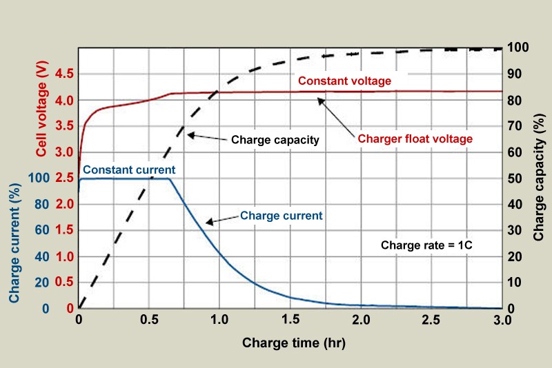
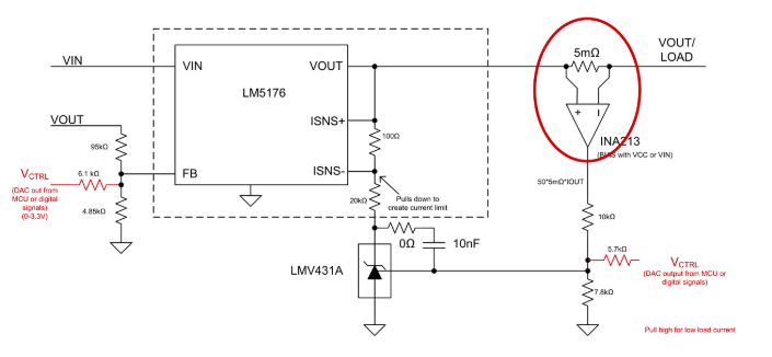
I'm using the LM5176 to design a CC-CV battery charger for a Li-ion battery. The battery ranges from 39V to 55V. The output of my AC-DC power supply is 48V DC. I have a couple of questions

  1. What will the CC-CV curve look like if I don't bias the FB or ISNS pins? Will the charge current taper as the battery voltage approaches 54V and enters C mode?
  2. I read a thread on using this part as a charger (https://e2e.ti.com/support/power-management/f/196/t/762488?tisearch=e2e-sitesearch&keymatch=Battery%20Charger%20(non-PE). It wasn't clear to me what the resolution was. Was the LM5176 breaking in some conditions and situations? And if so, what conditions caused this and what are the remedies?

Thanks,

Terence

  • Hi
    The responsible engineer is out of office now. He will reply by 4/23
    Regards,
    EL
  • Hi EL,

    I have still not heard from the responsible engineer about my inquiries

  • Hi Terence,

    Sorry for the delay. I just came back and I will take a look and respond to you tomorrow.

    Thanks,
    Youhao Xi, Applications Engineering
  • Hi Xi,

    Do you have any updates on the inquiry?

    Thanks,

    Terence

  • Hi Terence,

    I looked at your original post and I was confused by your questions. What do you mean by not biasing FB and ISNS pins? Why do you want not to bias these pins? Can you be specific?

    Thanks,
    Youhao
  • What I mean is, if I have a voltage divider connected to the FB pin and a current sense resistor on the ISNS pins setting the average output current, what will the CC-CV curve look like if I used this curcuit to charger a Li-ion battery.

    Also you didn't my second question about another user's post

    Thanks,

    Terence

  • I see what you mean. The I-V curve under CC-CV control looks like the typical, which is a rectangular shape: when the voltage is blow the regulation level, the circuit has the constant current. When the voltage reaches the setting point, the current falls vertically.

    Regarding the other post, it basically says that if you want to prevent reverse current during soft start, you should consider the LM5175.

    Thanks,
    Youhao
  • When it fall vertically is that a sharp drop or is it a tapered gentle slope towards 0A? And if so, at what rate does it lower the current?

    With regards to the second question, is there another way to prevent reverse current on the LM5176? the LM5175 doesn't meet my spec. Also is reverse current an issue with long soft start or will it occur no matter what I do?

    Thanks,

    Terence

  • Could you also explain how the current control scheme shown below works? It was suggested by a TI rep in a previous post

  • Hi Terence,

    Let me answer both your previous posts here.

    (1) the charging current will look like what you show in the graph. When I say falling vertically I meant in an I-V curve, with "I" in the x-axis, and V in the y-axis.

    (2) if you want to use the LM5176 bu also want to prevent reverse current, you can replace the boost high side FET to a Schottky diode. You should still need to use the BOOT2 and SW2 pins to remain full operation mode, but just replace the FET with a diode.

    (3) the diagram that you show in your 2nd post is for adjusting CC limit. The LM5176 has fix CC threshold. If you want to adjust the CC, that is the circuit to use. Then the external circuit (INA and LMV431) makes an external CC control. VCTRL is the handle to adjust the threshold. Increasing VCTRL the CC threshold is reduced.

    Thanks,
    Youhao
  • Thank you. That's very helpful. Just checking, is the reverse current that occurs if I use a FET harmful for the IC or the power supply that's powering the LM5176?

    Also, for the CC limit control diagram are the 2 instances of "Vctrl" the same? What I mean is, are the ends of the 5.7k and 6k resistor connected to the same DAC output from the MCU or are they controlled independently?

    Thanks,

    Terence

  • The reverse current is not harmful to the IC, but it may exert high voltage stress on the buck low side FET during switching off.

    These two "Vctrl" signals should not be the same one but independent from each other. The one on the left is to control CC, and the other (left one) to control CV.

    Hope this clarifies.

    Thanks,
    Youhao
  • Can you explain the "high voltage stress on the buck low side FET during switching off" a bit more? How does this come about?

  • The buck low side FET is the sync FET, and its normal operating current flows from source to drain. When the current reverse, the FET will see a current flowing from the drain to source. Then, when you turns the FET off, there will be turn-off voltage stress.

    During soft start, without DCM mode for the low side FET, its turn-on time will be very big (1-D, where D is the buck high side FET duty, and it is small during soft start). When the output is prebiased, this makes a boost in the reverse direction. Large current will be sucked out from the output battery, flowing into the input. Such large reverse current will cause excessive turn-off voltage stress on the buck low side FET.

    Hope this clarifies.

    Thanks,
    Youhao