We would like to measure Bode plot of bq25713.
Please tell me the injection resistor point we should put.
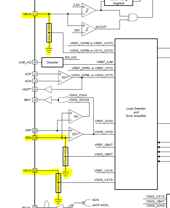
- During charging operation
Is it between VBAT and SRN pin?
- When BATFET is OFF
Is it between VSYS line and VSYS pin?
- During OTG mode
Is it between Vin line and VBUS pin?
Best Regards,
Kohei Sasaki