This thread has been locked.

If you have a related question, please click the "Ask a related question" button in the top right corner. The newly created question will be automatically linked to this question.

TL431: A application Question about TL431

Part Number: TL431

Hi Experts,

When coming into reading TL431 datasheet Fig 36. I found there might be a problem for this kind of design:

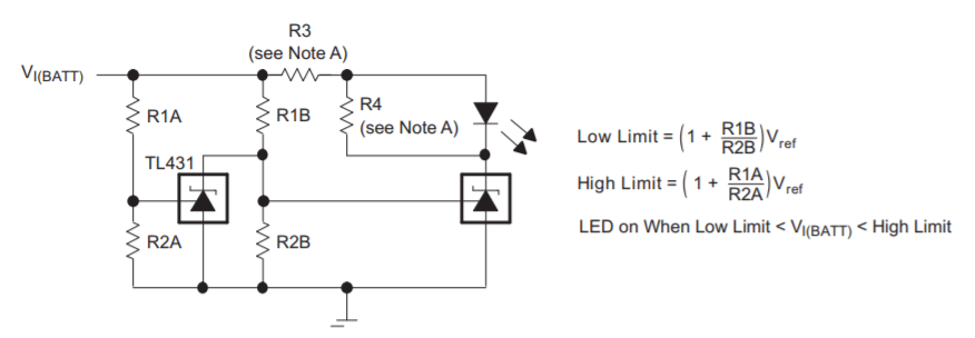
Since VI(BATT) is connected directly to a resistor divider to REF. When VI(BATT) is higher than Low Limit, voltage on REF will therefore inevitably be higher than 2.5V. As what i can consider, put R3 before first resistor divider(left one) can solve this. Could you please give a clarification? Thank you for your help!

-Wenhao 

  • Hi Wenhao,

    When VI(BATT) is higher than the lower limit , The cathode voltage divider of R1B/R2B will give the REF of the right TL431 a voltage higher than 2.5V. This is desired because the voltage will cause the comparator will trigger and the cathode of the right TL431 will be ~2V which turns on the LED.

    We do not want to put R3 before the resistor divider or else we lose the accuracy and have to add in R3 into the calculations. This is because R3 will have a voltage drop.

    Battery Voltage Left TL431 cathode voltage Right TL431 Cathode voltage LED
    Vi(BATT)< Low Limit ~Vi(BATT) ~Vi(BATT) OFF
    Low < Vi(BATT) < High ~2.5V ~2V ON
    High < Vi(BATT) ~2V ~Vi(BATT) OFF

    -Marcoo

  • Hi Marcoo,

    Thanks for your reply. Since this is the case, i have more question:

    1. Will REF pins sink current in order to keep this pin equals to 2.5V?

    2. If REF is higher than 2.5V, the TL431 will make internal darlinton pair saturated, thus performing like a comparator. How highest the voltage on REF pin can be? It does not specific in datasheet. 

    Thanks!

    -Wenhao

  • Hi Wenhao,

    this simulation might answer some of your questions:

    wenhao2.TSC

    Kai

  • Hi Wenhao,

    Kai's simulation helps show the functionality of the circuit.

    In regards to your questions.

    Yes the REF pin will sink current to keep the VREF around 2.5V. There is no ABS max voltage because its more of a CV until the ABS max current is violated. The TL431 VREF will be between 2.5V and ~2.6V when IREF is below 1mA. I would recommend to keep IREF below 1mA even if ABS max is 10mA. It is possible to design 1mA limit because you know the voltages on both sides of the R1B and R1A.

    -Marcoo

  • Hi Macroo,

    Thanks for your reply. This has solved my question.

    -Wenhao