This thread has been locked.

If you have a related question, please click the "Ask a related question" button in the top right corner. The newly created question will be automatically linked to this question.

LM5088: Clicking noise when power is applied to the DC-DC converter

Part Number: LM5088

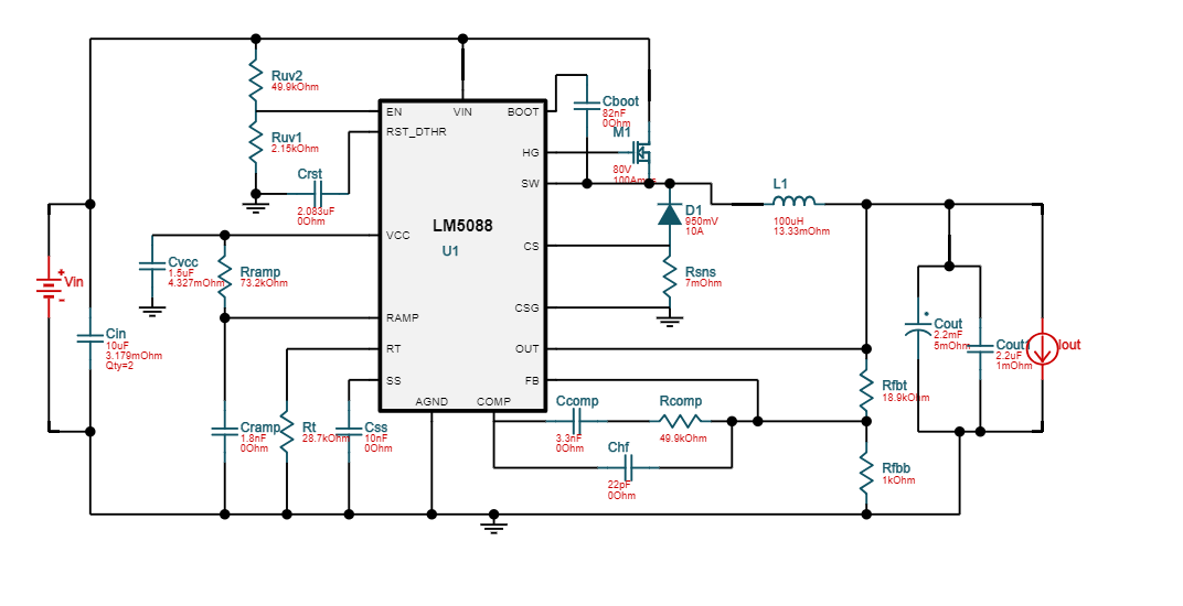
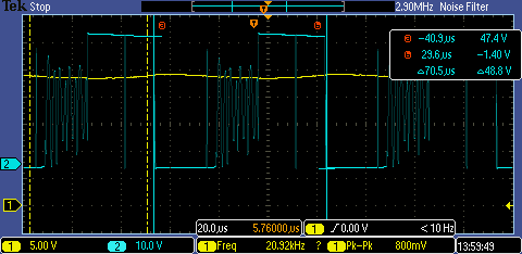
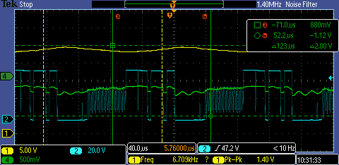
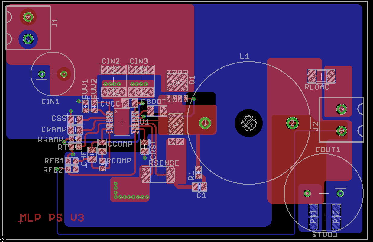
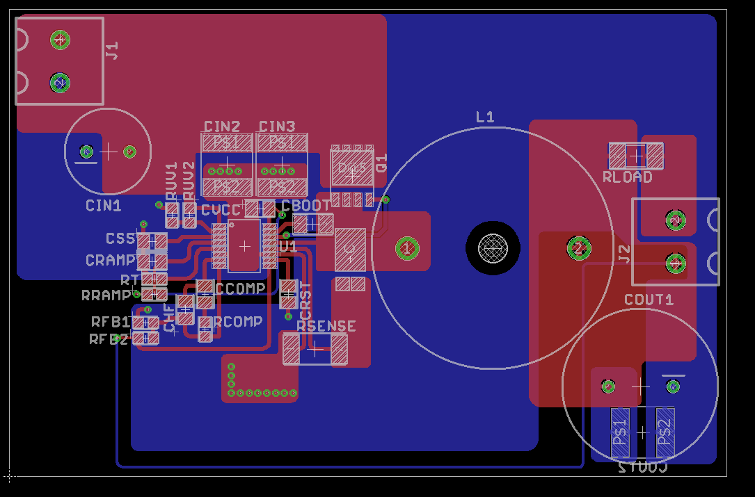
I have a LM5088-2 48V to 24V buck design that when I power on the device, I get a clicking noise somewhere on the board. I stuck with the autogenerated design but with a few differences.

The inductor is 100µH

The large output capacitor is 2200µF

Cboot is 33nF

Everything else is more or less the same.

Right now I suspect I have some form of over current condition.

I have tried lowing the Rsense resistor to see if the problem is over current and that didn't help.

I then tried removing Crst to see if that helped and it didn't

The reference design was generated with the following settings:

40 - 60 Vin

24 Vout

9A load max

  • Michael,

    Check the output of the controller to see if you see some oscillation. If so, confirm that it's at the same frequency as the clicking. If so:

    • Your smaller CBOOT may cause you to hit boot UVLO. Check to make sure the boot cap voltage (BOOT to SW) is above 3V at all times.
    • Please also check that you have good compensation values. You can use the quick start calculator to check.

    Please also share the schematic for further review.

    Thanks,

    -Sam

  • I will swap out the Cboot for a larger ones when I get the chance.

    I did find out that the clicking is replaced with the normal inductor wine when I went with a smaller Cout capacitor (2200µF -> 220µF). The frequency now gets higher the larger the load.

    The inductor wine is based on the switching frequency of the buck converter, right?

    Here is the schematic for the circuit board

  • Michael,

    Your clues make me think this may be a stability issue. Check if the output voltage is stable. The whine may be at the frequency of the output instability if this is the issue. In this case you will need to use the quickstart calculator to recompensate Rcomp, Ccomp, and Chf.

    -Sam
  • I connected an osciloscope to the load and the output was fairly stable at about 800mV peak to peak. I did find the frequency of the output to be ~8kHz at a 1A load and ~25kHz at a 2A load.

    I checked the switching frequency at pin 13 and found the frequency to be about 15kHz and there was some noise mixed in.

    Yellow is the 24V output and blue is pin 13 in the IC (SW)

    I'm having trouble downloading the quick start calculator, I get a site maintenance warning when I try to download the calculator.

  • Michael,

    This is strange. With an RT resistance of 28.7k you should expect a switching frequency of around 200kHz to 250kHz. I believe the issue is stability. Please recompensate using the excel calculator (direct link here and attached below).

    6710.LM5088_Quick_Start.xls

    -Sam

  • This is after switching the compensation filter to 25kHz per the quick start calculator.

    The load is currently ~2.4A but when I step it up to ~3.6A the power supply starts to shut off. I've lowered the Rsense to ~7Ω so I don't expect it to be an over current situation,

  • Output with the 15kHz compensation circuit.

    2.4A load

  • Michael,

    You should expect a switching frequency of around 220kHz. Please recompensate for a frequency of 220kHz. The lower frequencies (15kHz, 25kHz) are the frequencies of the instability which we are trying to eliminate.

    -Sam
  • The Rt in the actual circuit is 24.9kΩ to give a switching frequency of ~250kHz. Should I try and compensate for a higher frequency?

    And I did seem to have an over current condition for some reason. The voltage stopped dropping out once I shorted the reset pin to ground
  • Michael,

    Yes, compensate for a switching frequency of ~250kHz. Your crossover frequency should be no more than 25kHz but your switching frequency is 250kHz.

    The RES pin shorting to GND is a good datapoint. We'll look into that once you recomensate.

    -Sam
  • The board I was working on smoked itself after ~30 seconds under full load. I will rebuild the circuit with the circuit with the 25kHz crossover frequency and take another look at the output.
  • Michael,

    Keep me posted. Thanks,

    -Sam
  • For some reason the new board is unable to maintain 24V under load and I'm still having issues with the inductor whine. All of the parts are the same as the other board that was working.

    The voltage dropout is normally a result of the inductor being too small, correct?

  • Michael,

    Voltage drop can be a result of many things, including an inductor being too small. It could also be instability or current limit or some other issues. Please share your current schematic and some waveforms showing what's going on (voltage drops how with load? Linearly? All at once? Something else? What does the output voltage look like and does SW look stable at 250kHz?).

    I took a closer look at your layout. Here are my comments:
    1. Try cutting the CSG connection to the power pad. This and CG should have differential routing to the sense resistor which your layout does, but this connection to the GND plane under the IC corrupts this measurement.
    2. Try placing a 1uF ceramic cap close to the VIN pin of the IC connecting to the GND plane just above the IC to the left of CVCC
    3. The thermal pad should have vias. This helps with heat but more importantly provides a more direct path to the GND pin of the IC. Right now all return current must travel through the bottom layer to the CIN2 and CIN3 vias, then to the thermal pad to the GND pin of the IC.
    4. The placement of the RSENSE GND with relation to the CIN cap GND makes a large return path --> large loop which is bad for this high di/dt loop (adds inductance, ringing, overshoot, and possible coupling).
    5. Same issues as 4. but for the COUT GND. That's a long path which creates a large loop. It would be better to have a path directly back on the bottom layer.
    6. Is there a trace under the RT resistor? Make sure this is not connected where it shouldn't be.

    There's only so much you can do with those notes on your current board but they are worth considering for debug and your next spin.

    -Sam
  • for points 4 and 5, the final version of the board will be a 4 layer board instead of a 2 layer board. This will result in a large ground plane.

    That should solve those potential issues, right?

    The board I'm currently working with had some thermal compound to improve the heat sinking of the pad underneath the chip. Could that be causing some issues as well?

  • Michael,

    Yes, a solid GND on a mid layer will solve issues 4 and 5.

    Thermal compound will not be better than soldering the EP (exposed pad) directly to the GND plane of the board. This could definitely be causing your issues. Remove all thermal compound under the IC and solder the EP to the board.

    -Sam
  • This is the current board I am working with, I cut the CSG trace to the ground plane underneath the chip. I'm not getting the 24V output that I expect. Instead I am getting 4.2V with a very small load and that drops down further as I increase the load.

    R1 and C1 are currently not being used. They are there in case I need to add a snubber circuit.

  • Michael,

    Please try cutting the trace connecting CSG to the GND plane under the IC. This is probably messing with the current sense.

    Please confirm you've soldered the thermal pad to the IC.

    -Sam
  • I cut the trace and I'm reasonably certain that the thermal pad has been soldered to the ground plane beneath it. These parts are being soldered by hand so I can't be 100% certain though.
  • The blue signal in the previous image is the voltage at pin 13 of the IC.
  • Michael,

    Pin 13 is the switch node. This should be a square wave from 0V to VIN. There's something going on with your circuit but I'm not sure what it is.

    I recommend going back to WEBENCH and exporting a simulation file. Then check each pin and compare with your design. Which pins are not behaving as expected?

    -Sam
  • Michael,

    How's this going? I haven't heard back for a few days.

    -Sam
  • Unfortunately I have had to prioritize some different tasks and it will be a few weeks before I can get back to this project.

    Should I create a new post when I get back to this project or continues posting updates here?

  • Michael,

    I understand. You should post a new thread (this one locks after 30 days since the first post) but refer them back to this post for reference.

    I'll close this post. Thanks,

    -Sam