This thread has been locked.

If you have a related question, please click the "Ask a related question" button in the top right corner. The newly created question will be automatically linked to this question.

TPS65131-Q1: Overshoot on 5V when generating 10V and -10V

Part Number: TPS65131-Q1
Other Parts Discussed in Thread: TPS65131, UCD9090-Q1

Hello,

We are having some issues with the TPS65131.

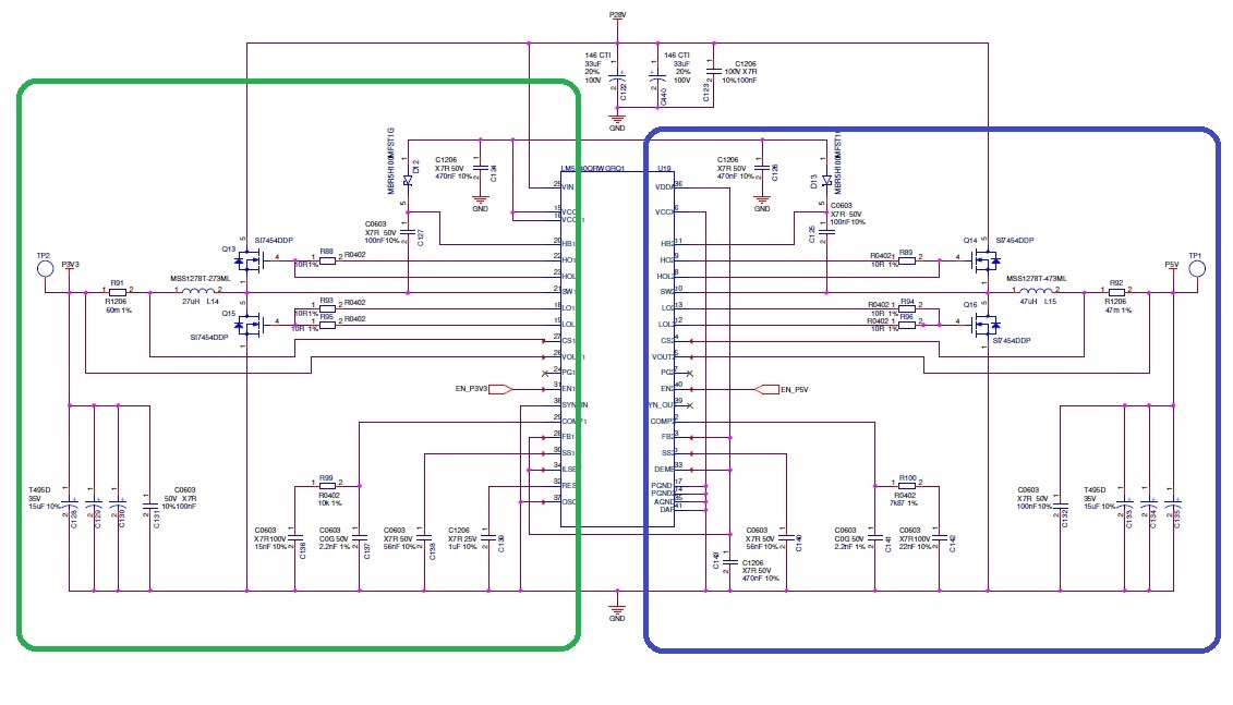
In our board design, we generate 5V and 3V3 power supplies from 28V input using the LM5140QRWGRQ1.
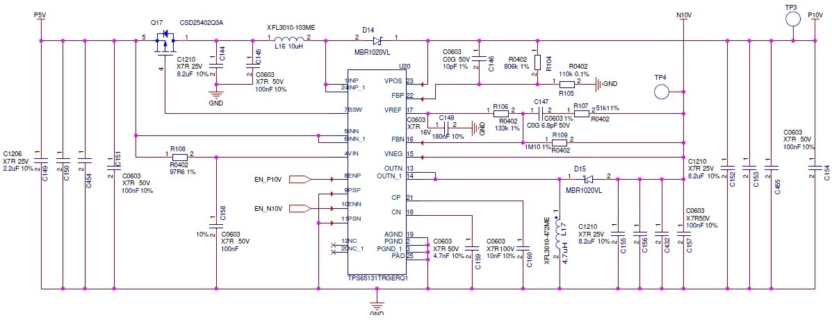
Then from the 5V, we generate a 10V and -10V voltage using the TPS65131.

We have sequenced the startup of those power supplies using the UCD9090-Q1.

Once the 5V is started, 10ms after we start the 10V and 15ms after the -10V.

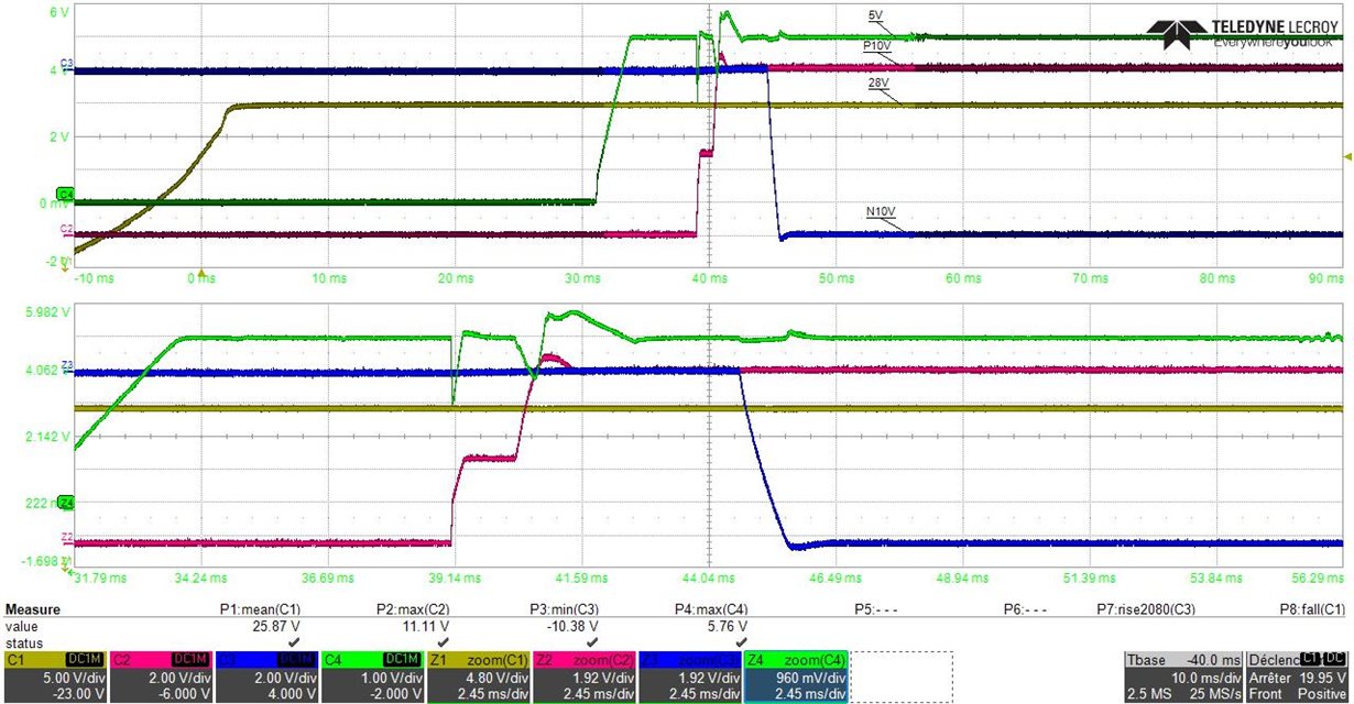
As you can see from the below oscilloscope print, when the 10V starts, there is an immediate decrease of the 10V, stopping the 10V raise (hence the step) and then an overshoot occurs once the 10V reaches its regulation state. For the -10V, the behavior is a little different but we still have an overshoot as you can see.

The schematic of our 3V3/5V design:

The schematic of our 10V/-10V design:

Any help would be appreciated.

If we can't fix that we might have to take a component from a competitor...

Clément

  • Hi,

    I have notified our expert regarding this topic. Please expect a response by 4/24/19.

    Thanks,
    Aaron
  • Hello Clement,
    From your description of the problem:
    ===========
    As you can see from the below oscilloscope print, when the 10V starts, there is an immediate decrease of the 10V, stopping the 10V raise (hence the step) and then an overshoot occurs once the 10V reaches its regulation state. For the -10V, the behavior is a little different but we still have an overshoot as you can see.
    ==========

    I wanted to clarify that the step you see at the 10V output from TPS65131 is not because of drop seen in the 5V supply input but because as soon as the EN_P10V signal is applied, the switch Q17 closes and immediately the input voltage minus D14 diode drop appears at the output before the boost converter even starts switching. So this is normal operation for boost converter of TPS65131 and this step will happen even if you provide the 5V input to TPS65131 from a bench top power supply.
    Having clarified above point, indeed the drop in the 5V input supply should not occur when boost converter of TPS65131 is enabled and this drop is most likely concurring because the input supply is not able to deliver the in-rush current needed to charge the capacitance at the TPS65131 boost out put. Can you please experiment by putting a big capacitance close to TPS65131 input in parallel to C149 or C144? You should see an immediate reduction in the voltage drop of the 5V input. This can also be happening due to too much trace inductance between the 5V supply source and the TPS65131 input. I will also contact the appropriate group within TI which supports LM5140QRWGRQ1 so that they can review that section of the circuit also to provide any further feedback.

    Now about the brief overshoot at TPS65131 output: some overshoot is going to be there at start up but I think you may have a bigger overshoot because you are using a larger 10uH inductor at L16 where as actual recommendation in the datasheet is for a 4.7uH. A bigger inductor slows down the loop response time and you may have a bigger overshoot because of that. You may also be able to reduce overshoot by adding more capacitance at TPS65131 boost and inverting converter outputs. I am not sure if there is one 8.2uF capacitor at these outputs if there are three.
    One other thing I noticed int eh schematics is that VREF decoupling capacitor (C148) is recommended to be 220nF in the datasheet.
    I hope that these suggestions are helpful in resolving the issues you are seeing.
    Kind Regards,
    Liaqat
  • Hello Clement,

    Suggest using a 5V bench supply and remove the LM5140 from the input.  Check that the bench supply can supply the instantaneous start up current of the TPS device.  If the issue is due to the input voltage of 5V dipping at start up (output of the LM5140), I would check that the LM5140 is not hitting current limit? 

    If it is not, I would look into speeding up loop response of the LM5140 such that the input voltage of 5V is not dipping upon start up of the TPS device.

    Hope this helps?

    David.

  • Hello,

    Regarding the first post of suggestions, we mostly tested those things already before asking and it didn't lead to any better result.

    We are going to check your last suggestion David, thanks.

    Clément