This thread has been locked.

If you have a related question, please click the "Ask a related question" button in the top right corner. The newly created question will be automatically linked to this question.

LM3424-Q1: Problem in calculation of few resistance values and Vhys value for buck mode.

Part Number:

We are using LM3424 in Buck Mode to get an output of around 11.25V. The nominal input voltage is 24V, but can go as high as 32V or as low as 20V.

We have bought LM3424 IC and we are implementing the circuit , given at the end, under application heading, in data sheet of LM3424 for buck mode.

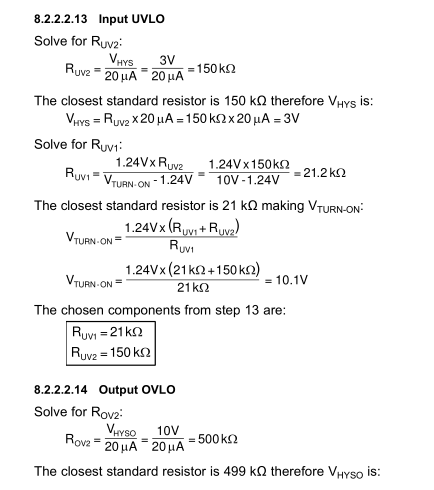
we need to know how you have calculated the value of Vhys , RESISTANCE VALUE viz Ruv1 Ruv2 Rov1 Rov2 etc. for INPUT UVLO and OUTPUT OVLO for buck mode.

like in data sheet they are taking one resistance value (assumption) solving for Vhys and then again taking THAT Vhys value to solve for RESISTANCE like how can we assume as such.

if its by default or depends on some internal circuitry please let us know 

and kindly tell the calculation of Vhys , RESISTANCE VALUE viz Ruv1 Ruv2 Rov1 Rov2 etc. for INPUT UVLO and OUTPUT OVLO

Thank you

  • Hi Vaibhav,

    The specified hysteresis voltage for the fault along with the hysteresis current of 20uA will determine the ROV2 and RUV2. Then from ROV2 and RUV2 you will calculate the ROV1 and RUV1 for the over-voltage and under-voltage.

    Please see example of the Buck Boost in section 8.2.2.2.11 for input voltage UVLO equation and section 8.2.2.2.12 for the output OVLO equations. The Buck Boost OVLO sensing circuit is the same as the the Buck with a PNP transistor.

    Section 8.2.1.2.11 also describe the OVLO and Section 8.2.1.2.12 describe the UVLO.

    Thanks Tuan
  • Hi Vaibhav,

    I have a miss typed on the sections above. Section 8.2.2.11 and section 8.2.2.2.12 should be 8.2.2.2.13 and 8.2.2.2.14 respectively. Section 8.2.1.2.11 and section 8.2.1.2.12 should be 8.2.1.2.13 and 8.2.1.2.14 respectively.

    Thanks Tuan
  • Hi Tuan,

    after gone through the sections then only the doubt raises .I am attaching the image please see,

    first you took Vhys=3V right? then you calculated Ruv2 , then again you took Ruv2 to show Vhys=3V. why?  

    the question is why you choose Vhys=3V here, what is the base of this assumption?

    same case is with Rov2 or you can say OUTPUT OVLO. Vhyso=10V HOW? or WHY?

    Please correct if i am wrong somewhere.

    Or will this be the DEFAULT values for this BUCK MODE Irrespective of the other parameters.?

    kindly confirm soon.

  • Hi Vaibhav,

    This is a standard way for us in term of recalculating the Vhys.  Since there are instances where the calculated value is not a standard resistor value and that's all.  You can choose Vhyst with different value if you like but understand that when you first start, the current will be drawn and the input voltage can droop due to power line impedance losses and that's why we chose 3V.  For instant if you choose 2.9V then Ruv2 = 2.9V/20uA = 145K but there is no 145K and the closest 1% standard value is 143K or 147K then you use the value that you select to recalculate your actual Ruv2.  If you choose 143K then the actual Vhys = 143K x 20uA = 2.86V. 

    Again, you can choose whatever you wish for Vhys for undervoltage and over-voltage you wish but understand that input votlage will droop as you draw current especially for high power system.  As far as the over voltage is concern, it's a current source that drive LED's and if there are different loads thenthen the LED voltage can be different and or if you have an open circuit then the controller will turn off until the hysteresis is reached to protect itself. 

    These are very fundamental things for designing power circuit and I think you need to understand and educate yourself more about these tradeoffs prior to designing you system. 

    Thanks Tuan