This thread has been locked.

If you have a related question, please click the "Ask a related question" button in the top right corner. The newly created question will be automatically linked to this question.

LM3424: INDUCTOR RIPPLE CURRENT

Part Number: LM3424

We are implemeting the circuit for the BUCK mode , given at the end of data sheet of 3424 under the heading application.

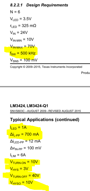
can you please tell why you have chosen the value of inductor ripple current to be 700mA ,though the value should be 20-40% of the INDUCTOR CURRENT say here this is 1A.

  • Hi Vaibhav,

    Did you miss read? We specified the swtiching frequency to be 700KHz. I did not see anywhere that we specified the ripple current to be 700mA.

    Thanks Tuan
  • Hi Tuan,

    Sorry if i  miss read , but this didn't clear the confusion .

    I am attaching the image please see.Some portion of the image is highlighted

    kindly confirm how you chose those values except frequency.

    My question is say for example frequency 200KHz , now how can we choose ripple current for this frequency ? it should be 20-40% of the average inductor current . And my Average inductor current is 1A.

    because in section you stated there is frequency 500KHz and iL-pp(ripple current)=700mA.( kindly see the attached image).

    JUST TELL US HOW TO CHOOSE THIS VALUE FOR OUR DESIGN PARAMETER STATED EARLIER and HOW YOU CHOOSE THE HIGHLIGHTED VALUE IN THE IMAGE ATTACHED?


    quick reply will be appreciated.

  • Hi Vaibhav,

    You mentioned Buck mode in your original question.  What you listed here is section 8.2.2 which is for Buck Boost.  Which one is correct?  I've answered you in other posts and it's best if you read the data sheet and really familiarize yoourself with power design.  In section 8.1.1 of the data sheet, we mentioned mentioned some criteria for inductor selection based on the topology that you use.

    Thanks Tuan