This thread has been locked.

If you have a related question, please click the "Ask a related question" button in the top right corner. The newly created question will be automatically linked to this question.

LM2679: Doesn't reach full output at full load

Part Number: LM2679

Hi Everyone,

I am trying to use the LM2679 to power vacuum tube heaters at 12.2V, 2.7A with an input voltage of 22V. Everything works as expected until I load the circuit to around 1A. Above this, the regulator fails to achieve full output (usually around 7-8V). I've tried quite a few things like raising the current limit from 5 to 7A, changed the soft-start cap from 22uF to 100uF, reduced the output cap and removed the second filter. All have seemed to have helped slightly.

I've made some odd observations that may help one of you with more experience with this chip recognize what is going on:

  1. The time it takes for the voltage to ramp up seems related to the load current. At 300mA it seems instant, but at 1A it takes 30 seconds of more to get close, at 2.7A we get to around 7-8 max after minutes.
  2. I will measure no voltage output at either the diode or main cap for a few seconds after startup. The time appears related to load as well.
  3. This circuit has a standby mode that will reduce the voltage to 8V (actually the circuit starts this way). If I throw the switch for full output before the voltage reaches 8V, it doesn't change the rate of voltage increase...in other words, this doesn't appear to be related to the feedback.

Does anyone recognize this behavior? Anything I should try to get this working? I feel like I'm kind of out of things to do with so few external parts.

Thank you!

  • Liquidair,

    It seems strange that it should take anything longer than tens of ms to ramp the output voltage up in a typical application. Please share your schematic and layout and we'll take a look.

    -Sam
  • Hi Sam,

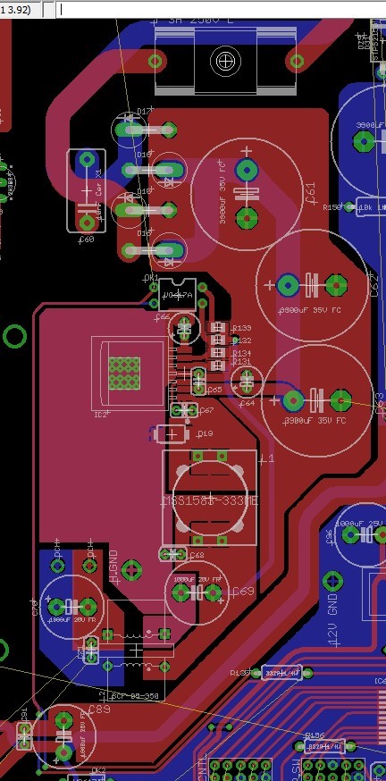
    Thank you for the quick reply! Please see attached. As of right now, there are a few value changes from the schematic:

    1. R186, was 7,5k now 4.64k (attempting to eliminate current limit)
    2. C126 was 1000uF, now 100uF
    3. L5, C124 removed.

    LM2679Schemo.pdf

    Thank you again!

  • I observed something else weird today. At full load and in standby mode (8V), the voltage measured at the output is about a volt less than measured at D19 but eventually (like after minutes) will get to 8V. When I flip standby off (12.2V), the voltage again trails by a volt or so. Is that perhaps telling us something like the inductor is the wrong value or we are triggering the "large hysteresis in the current limit" that the DS talks about on page 13 (section 8.1.9)?
  • I think that a 22uF is rather large for a SS cap. The leakage may prevent the SS voltage from coming to its normal value.
    I would try to remove the SS cap as a test and see if you get full voltage.
    If you need such a large SS time, you may need to use a ceramic cap.
    It looks like you have a total of about 2000uF on the output. This is a little large as well.
    You may also try removing one of the 1000uF output caps and see what happens.
  • Frank De Stasi said:
    I think that a 22uF is rather large for a SS cap. The leakage may prevent the SS voltage from coming to its normal value.
    I would try to remove the SS cap as a test and see if you get full voltage.
    If you need such a large SS time, you may need to use a ceramic cap.

    Thank you Frank! Unfortunately, with the SS cap removed, the core issue remains, although, this did appear to eliminate the issue where the voltage remains at 0V for some time. The only reasoning for using the large SS time is because tube heaters have a much lower resistance when cold, long is good in this case.

    Frank De Stasi said:
    It looks like you have a total of about 2000uF on the output. This is a little large as well.
    You may also try removing one of the 1000uF output caps and see what happens.

    Yes, I've tried this. At first I lowered them both to 100uF, then I removed the entire second filter and left a single 100uF which is where it stands now. Same results although the issue appears to be slowly improving with each tweak.

    I still noticed the 1-1.5V drop across the inductor today. With a max DCR of ~40mohm, that implies 25A of current flowing, no? 

    Is there anything else this could be? 


  • I am not sure how you are measuring the drop across the inductor, but you would need to look at it with a scope. It would be good to see some waveforms of the switch node and vout under various conditions. I would check the current rating of the inductor to be sure it is good to at least 5A. It is also a good idea to double check the values of the other components and that the connections are good. Also, you may need to get an EVM from TI and use that as a baseline to make your changes and see where the problem comes in.
  • Frank De Stasi said:
    I am not sure how you are measuring the drop across the inductor, but you would need to look at it with a scope. It would be good to see some waveforms of the switch node and vout under various conditions.

    Thank you again Frank! I'm measuring with a DMM, which I wouldn't think would be ideal but it always shows exactly my calculated figures of (8.1V in standby, and 12.2V in normal mode) with light loads, and with intermediate loads it will eventually get and stop there after a few minutes, which says to me that its accurate enough to show us something. With the heavier loads, I simply go back and forth between the diode and output nodes and the output node always lags by around that one volt. When the diode node maxes out, the output node still slowly rises as there's plenty of time to probe back and forth, although oddly, it sometimes seems that the output node will suddenly make a fast jump and suddenly it will top out at the 8.1 or 12.2V.

    Frank De Stasi said:
    I would check the current rating of the inductor to be sure it is good to at least 5A.

    The inductor is should be fine, listing an Isat 10% of 7A. It was much beefier than the ones Webench kept spitting out.

    Frank De Stasi said:
    It is also a good idea to double check the values of the other components and that the connections are good.

    Ya, I went ahead and just resoldered everything to be sure but I didn't quite finish in time to test tonight.

    Just before I did that, I was wondering if maybe the small 100nF ceramics were an issue, maybe trying to draw very high current spikes through the inductor. Oddly, I found that removing those caps actually made things worse. The past day or so, it seemed like I could, if I waited long enough, get to the nominal voltages at full load, but after removing them I found I was back to square one where we were topping out in 9-10V range. Could that imply that we might have too high an impedance at the switching frequency and maybe it would be best to try some big ceramics?

    I'll get you some scope shots tomorrow. Anything in particular you want me to try to grab?

    Thanks again for your help!

  • I would stick with using a DMM on the output and using a scope on the diode node. Scope shots of the diode node under
    various conditions would be helpful.
  • Thank you again Frank!

    Unfortunately, we'll have to wait a few days. Today after resoldering everything I was only able to get 2V max at half load (1.8A...300mA was fine), and my desoldering gun's motor pooped out. I'm only damaging the board with the soldapult, so I'm just going to wait until the new tool arrives. I'll get some new parts too in the interim to see if that's not it.

  • Ok, I've got some new info. First, attached are some scope shots.

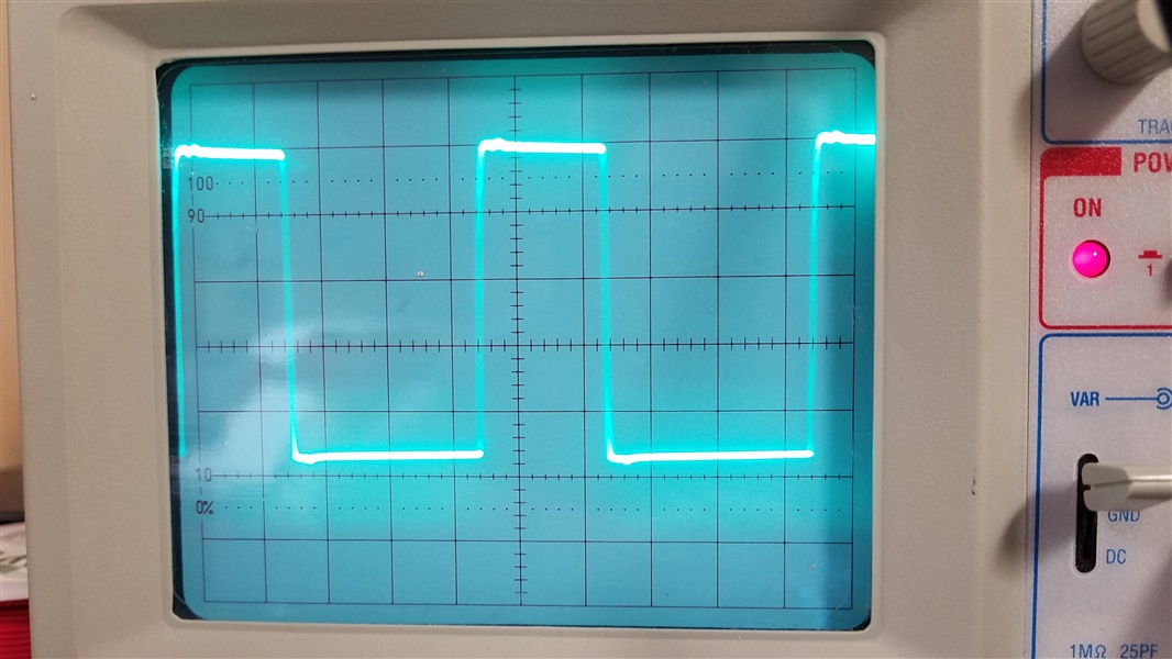
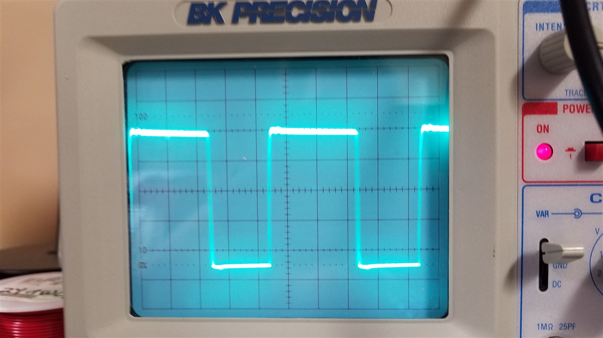
    8V Output Diode Node12.2V Out Diode Node

    These are all 5V/d and .5us/d with a 1x probe with a diy ground spring that I made today with a load current of 1.8A. The 1st pic is in 8V mode, the second in 12.2V mode. What is interesting is that before I made the ground spring, we were getting the same old slow rising output voltage... but with the spring, the voltages reach their nominal values almost instantly. Funny enough, if I remove the scope probe after the voltage has risen to 8V in standby mode and set the unit to a 12.2V output, the voltage will actually fall from 8.1V to about 7.5 and will never rise to 12.2V. The second I put the scope across the diode, the voltage instantly rises to 12.2V.

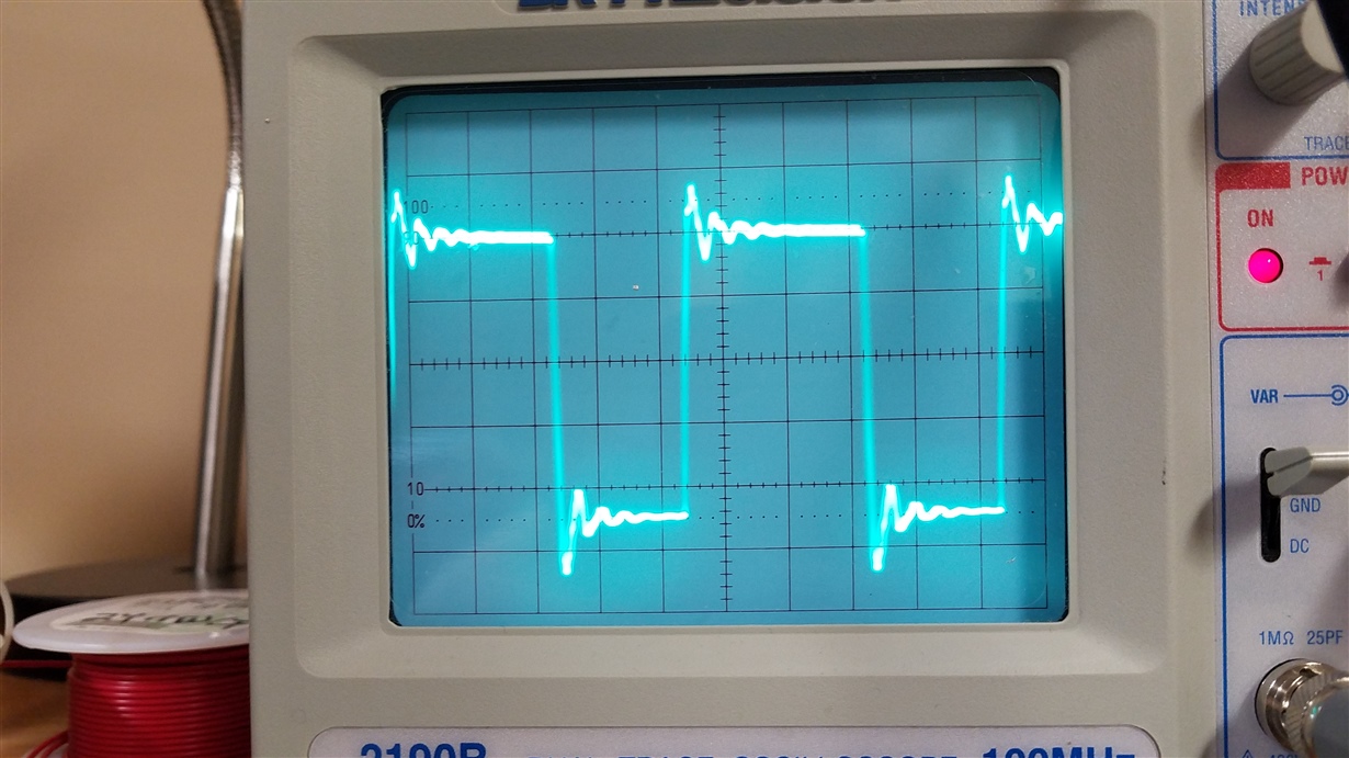
    12.2V Out Diode Node with Ringing

    Now, the third picture is in 12.2V mode but I'm not making great contact with scope probe. I believe this shows us more of what is going on when there's no scope. I notice that when I can make the ringing appear like this the output voltage drops to 11.6V. If the scope shows a clean square wave like the first two pics, then the output voltage immediately jumps to 12.2V again. 

    My guess is the spring/probe are adding just enough capacitance to snub any instability in the IC output. Is there anything else that it could be? And if so, what do I need to do in the redesign to ensure I tame this ringing/instability in the first place?

    Another "clue" might be that before I took these shots I was playing with the bare-bones setup with only one of the 3300uF caps in place and no Cinx. I was only able to get around 2V output, but I found that by inserting Cinx and an OSCON 47uF Cin I could make the output voltage jump to 4-5V. Any clue what this might be? This suggests that my input layout might be playing a role too, such as how the input/output grounds are only joined at the GND pin trace? 

  • Ok, I think I've captured it finally by using the 10x probe setting and a different spring: a cycle is missing. See below.

    8V Low Voltage Diode Node

    I took this pic while the voltage was doing it's slow ramp up thing (~5V). Last night I was able to get the circuit working as expected (and at full current) if I touched a small film cap across the diode...100pF to 330pF all worked. If I touched the film cap across the diode while observing the scope, we would see another positive cycle where the spike appears in the image above, and instantly the voltage jumps to the correct value. When the cap is removed, we again see the above image and the output voltage drops.

    Interestingly the cap must be directly across the diode for the circuit to work properly. From the diode node to ground pin and input ground didn't work (as shown in the EVAL kits). 

    What's going on here? Based on the scope, it appears to happen when the diode stops conducting, as if the controller is getting messed up and misses the next switch turn on. Ground bounce?

    Or, I'm beginning to suspect the diode (V8PA10) itself might be playing a role as it has a very high capacitance (850pF) and high reverse current, and they do not list the recovery time (which I assume means it is rather poor). Can the diode be playing a role here or is what we are seeing something else? 

  • Sounds like you may have a bad connection some where.

    I would try to get an EVM from TI and see if you can start with that and

    get your application working.

  • Hello,

    Did you have a chance to look at the TI EVM and see if you could your component selections working?

    Could you also confirm the inductance value and the output capacitor ESR used for this design? Based on the last waveform that you shared, I want to verify that your component selections are enabling a stable applications circuit.

    Thank you,
    Katelyn
  • Katelyn Wiggenhorn said:
    Did you have a chance to look at the TI EVM and see if you could your component selections working?


    Hi Katelyn. No, I haven't. The EVM looks to be made for fixed versions, I'm using adjustable. Plus, I'm using the components following both the DS and Webench, so I'm sure that it's not that.

    I actually *almost* got it working by soldering desolder braid between the input ground and the ground plane between the diode and the IC. It worked fine immediately after soldering, but when I came back a few hours later it would get to 90-95% of output. 

    Katelyn Wiggenhorn said:
    Could you also confirm the inductance value and the output capacitor ESR used for this design? Based on the last waveform that you shared, I want to verify that your component selections are enabling a stable applications circuit.


    Inductor is either 22uH or 33uH, I've tried both. For the output cap, I have a 47uF OSCON in there now with an ESR of 27mohm.

    Another odd thing is that if I bend the input cap C65 towards the IC we get a higher max voltage, so I suspect the issue isn't a problem with the output but rather the input.

  • Hello,

    In order to further test your idea about the input ground, you could try to scratch the ground plane of the input and flip the output capacitors to reference this same ground polygon.

    Best Regards,
    Katelyn
  • Hello,

    Did yo get a chance to try this experiment?

    Thanks,

    Katelyn

  • Hi Katelyn,

    No not yet. I also have boards on the way with a new layout to test. I'll post with the results!

  • Hi,

    Thank you for sharing this update.  I am going to close this thread at this point.  But please open a new thread or respond to this post once you get the new results!

    Best Regards,

    Katelyn