This thread has been locked.

If you have a related question, please click the "Ask a related question" button in the top right corner. The newly created question will be automatically linked to this question.

BQ24610: BQ24610 control pin when no load

Part Number: BQ24610

Hello,

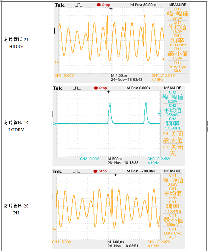
      my project is used in DC input 15V, charging is full of 12.6V charging circuit, I have two doubts, the first when I am empty, my two different items of boards HIDRV and LODRV and PH feet The switching frequency is different. The following is the waveform intercepted by the oscilloscope in my test. The second doubt is that the battery voltage I set is 12.6V, but the battery voltage I am full is 12.5. I have read the specifications and specifications of BQ24610. The 0.5% of the scale is a bit wrong. Can you give me the answer?

  • Hi,
    Can you re-attach the scope captures? I cannot see the attachments.
    For charge regulation accuracy, you want to look at VFB voltage, and the 0.5% spec will be based off of that, not the SRN voltage. Sometimes there can be inaccuracy in battery voltage regulation if there is too much impedance between where the charger senses battery voltage, and the actual battery which can cause an artificial voltage drop that tricks charger into thinking charge is complete. Then when current is terminated, voltage drop disappears and battery is not as fully charged as expected. You can also try decreasing termination current to more fully charge battery.
  • will reply on other thread containing same question.
  • Hello Kedar Manishankar,


    when the lithium battery is working normally, the frequency of 19 and 20 and 21 feet is about 600kz. When the lithium battery is not connected, the frequencies of the three feet are the same, and the two different boards appear different. The frequency, I am very confused.

  • Hi,
    It looks like the HIDRV is not stable, causing PH to dip. It is possible that this has something to do with BTST not being able to drive the HSFET on properly during the high cycle, causing LODRV to keep turning on to refresh BTST charge. Is it possible for you to share schematic? One other step would be to evaluate on EVM board, and configure it for your settings, as this board has been validated as a correct solution. You can test on EVM according to your 15V input, 12.6V battery application.
  •   Hello Kedar Manishankar,

    I don't have the EVM of bq24610. The parameters on my circuit diagram are the same as the EVM of BQ24610. The only difference is D1. My diode can pass 100ma current. You can pass 380MA. The diode I use is PC32PF3000A1EP. I can pass 100MA, I wonder if it is for this reason. But I am surprised that it is normal when bringing a battery.

  • Hi,
    It is possible, as your output voltage is close to input voltage, duty cycle will be high. Means that HSFET will be on longer than LSFET, and as BTST cap charges during the LSFET on time, the diode limiting continuous current could not be enough to charge BTST cap in this small LSFET on time interval. Are you using the same Q3 and Q4 as the EVM as well? High Qg can affect gate drive strength to turn on these FETs.
  • Hello Kedar Manishankar,

    my Q3 and Q4 use a lower gate capacitance, I checked the QQ of QQ and Q4 and Q4 of Q4 is 34nC, Q3 and Q4 on my board are 10nc, I am thinking about whether it is my board D1 The current limit caused, my D1 current limit is 100MA, yours seems to be 300MA, I can't apply for BQ24610deEVM here, I can't verify it, I can only test it on the board we painted ourselves in the last century.

  • Hi User,
    A good check would be to swap out the diode. I noticed you posted a couple of other questions on the same part, and was checking in to see if this issue still persists, or if you were able to obtain an EVM board to test?
  • Hello,

    I would like to ask the TTC pin of BQ24610, can the timer and termination current be in parallel? Which one has a higher priority in parallel? Or timer and termination mode is independent!

  • Hello,

    The charge safety timer and termination current are always in parallel as long as an appropriately sized capacitor is placed on the TTC pin.

    As far as priority, that depends heavily on your system parameters, i.e. Safety Timer setting, Termination Current Setting, Charge Current, Battery Capacity, board layout/connections, etc. For example, it is possible for the safety timer to hit first if the battery is large enough and the safety timer setting is short enough. The inverse is also possible.


    Regards,
    Joel H