This thread has been locked.

If you have a related question, please click the "Ask a related question" button in the top right corner. The newly created question will be automatically linked to this question.

UCC256302: UCC256302 issue

Part Number: UCC256302

Hi Sir

we have above questions need your help, pls help to check it,tks!
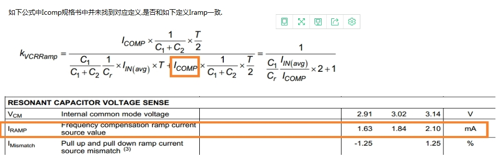
(1)VCR Pin:

The corresponding definition is not found in the Icomp specification in the following formula. Is it consistent with the definition of Iramp as follows?

(2).This IC specification is defined as the operating frequency range 35KHZ-1MHZ;

Is it possible to set the maximum and minimum operating frequency separately? The current test boot frequency is 700KHZ.
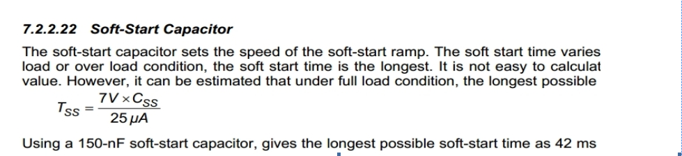
(3)Soft start

At present, the Css capacitor is 0.22uF, and the actual test soft start time Tss is only 22ms, which does not correspond to the actual calculated value.

(4)At present, the integrated transformer is used. Parameters: transformer leakage inductance 52uH, inductance 480uH. Resonant capacitor 824. SS pin capacitance 0.22u. RVCC-SS pin divider resistor 750K/200K, VCR voltage divider detection capacitor 101/222, ISNS current sense RC Parameter 100PF/255R, BLK setting 340V start. BW pin is not connected. Vcc is set to no load 15V. At present, the normal working frequency of the prototype is idling at 60K, the output voltage is set to 5V, and the actual value is 4.5V. The load will drop. Please help us to see if there is any unreasonable or need to adjust?

  • Darren

    Answers to your questions are below

    (1) You are correct, Iramp is the same as to Icomp

    (2) UCC256302 does not need to have minimum and maximum frequency limits like previous generation LLC controllers since the hybrid hysteretic control helps it avoid ZCS mode. Details are in this app note www.ti.com/.../slua834.pdf . If you need to maintain operation within a certain frequency range for other reasons, we recommend designing the power stage component values to insure that the converter stays within the desired frequency range over the operating conditions

    (3) This equation is a worst case calculation. Section 2 in this app note (page 2-5) www.ti.com/.../slua836a.pdf explains in more detail how the soft start function works

    (4) From your explination it sounds like the capacitor values in the VCR voltage divider are 100pF and 2.2nF. The bottom capacitor may be too small, we recommend increasing it to see if it solves this issue. The voltage on VCR pin should be under 6V, so if it is exceeding this value it may be preventing the converter from decreasing frequency. This app note has further recommendations on the VCR pin design on page 13 www.ti.com/.../slua836a.pdf

    Best Regards,
    Eric