This thread has been locked.

If you have a related question, please click the "Ask a related question" button in the top right corner. The newly created question will be automatically linked to this question.

LM3410: The output capacitor value

Part Number: LM3410


Hi Team,

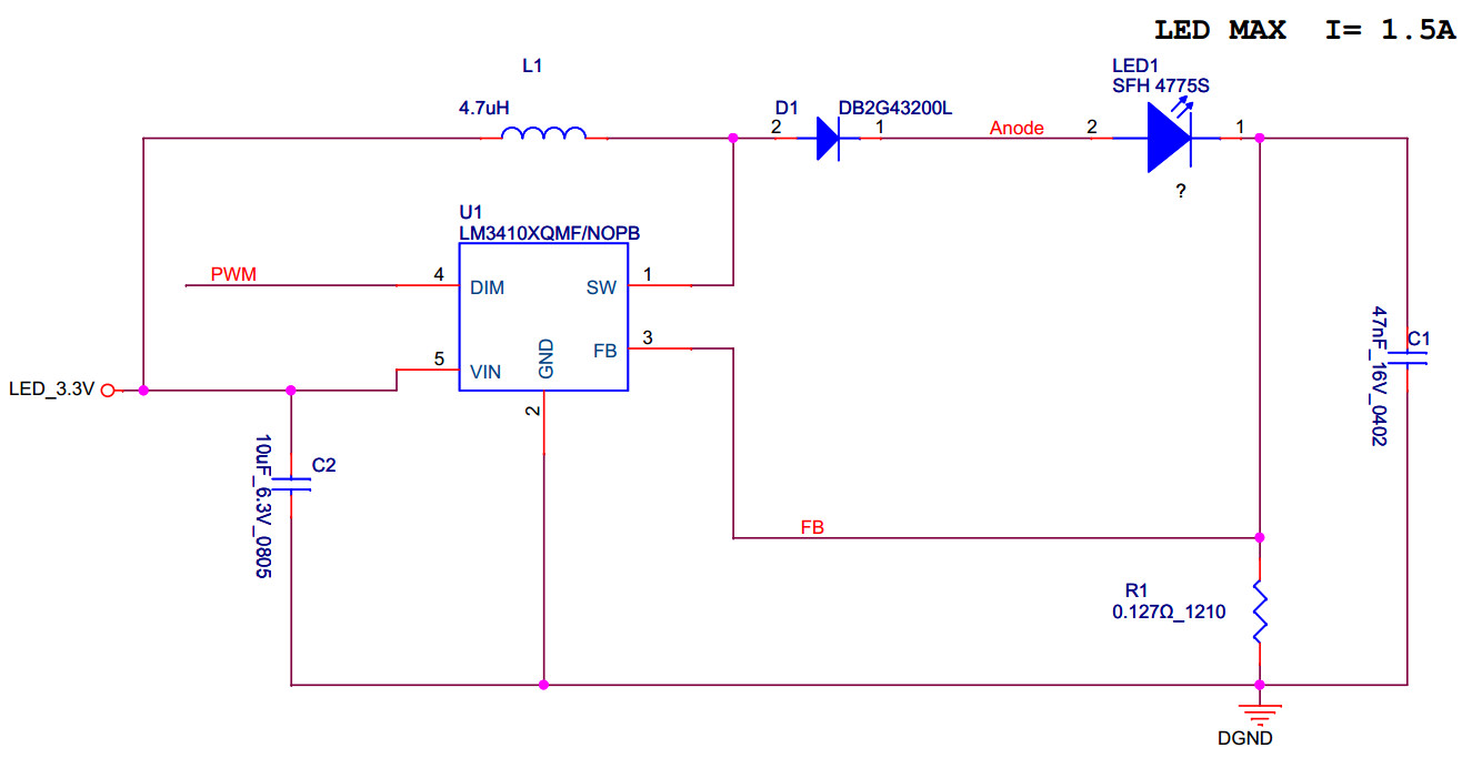
Please kindly help to check the schematic, especially the output capacitor.

We think the output capacitor nF level is very small in common DC/DC application, but according to equation28,30 in data sheet, the result is nF. 

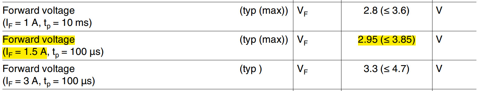
Our Vin=3.3V. LED VF as below, Vout=4.04V. Efficiency=0.9. Fsw=1.6M. LED dynamic resistance=2.

Thanks

  • Hello Daniel,

    First, where did the dynamic impedance come from? I found a datasheet with the SFH 4775S P.N. and get about 0.3 to 0.35 ohms between 2A and 1A Vf. Recalculate the output capacitor with a correct dynamic impedance. Dynamic impedance can be calculated as the slope of the Vf versus forward current (example, ((3.1V-2.8V)/(2A-1A))). The curve in the datasheet I looked at is lin/log and not very fine in resolution.

    Vin is 3.3V, why is Vout 4.04V? Also, with a boost configuration, there will be output when the LM3410 is off due to the boost feeding the output. When the LED is hot the Vf will drop making this worse. You may want to consider a SEPIC at these voltages (even though it's more complicated and less efficient).

    Best Regards,
  • Hi Irwin,

    Thanks for confirming the dynamic impedance.
    Vout comes from the max VF(3.85V)+0.19V=4.04V

    Re-calculate equation28 and 30 by RD=0.3
    I get C2>0.276uF.
    We concern, Why the output capacitor is smaller than common DC/DC Vout bypass capacitor?

    Thanks
  • Hello,

    There are a few things here. 250 mV of ripple was chosen for the example where Vout is 14.6V, your much lower so that ripple will be very high for a single LED.

    As for being small compared to a Vout DC/DC converter, the DC/DC converter is regulating voltage, it is part of the stability. If the load changes the bandwidth has to be able to adjust to prevent overshoot or undershoot. Hysteretic DC/DC converters can get away with much less output capacitance. As for a current regulator it doesn't matter if the voltage varies except for current ripple which is at a much higher frequency then the control loop of a voltage regulator. If the voltage varies it's not critical, it's just trying to keep current constant.

    If may be easier just to pick and output capacitor, say 2.2 uF (more or less) and just measure the ripple current. If the ripple current is small estimations in the math can be made to get close, if the ripple current is higher it gets more complicated because the dynamic impedance is changing.

    You will have another problem and that is the Vout of your design. You need to look at the absolute minimum Vout which is Vf minimum and also when at your maximum operating temperature. If Vin is 3.3V, diode Vf is 0.2V (when hot) and Vf of the LED is at its lowest voltage you can run into several issues. One being it will never turn off, even when the switcher is not switching. If Vf can get below 3.1V you can run into a failure mode where positive feedback causes the LED current to increase as it heats up which in turn causes more current.

    Best Regards,