This thread has been locked.

If you have a related question, please click the "Ask a related question" button in the top right corner. The newly created question will be automatically linked to this question.

LM3410: help with implementation

Part Number: LM3410

Hello,
I am currently designing power management for a small single-cell Li-ion LED lighting.

- I use a LM3410 in Y version (525 KHz)
- 6x in serial LED Seoul STW9Q14C each : 3V / 100mA / dynamic resistance 4 Ohm. Datasheet : seoulsemicon.com/.../5630_STW9Q14C_Rev2.0.pdf

To begin my tests I put into practice your typical application circuit that you provide on page 1 of the datasheet.

See the drawing with the component values I used :

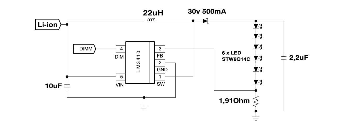
However my tests are not conclusive, I get only 50mA and 16,7V output, the LEDs are very underpowered. I tried to decrease the value of the resistance that allows to choose the current but it had no impact on the output.

Where do you think the problem comes from? I would not have taken the good value of inductance?

Thank you very much for your support,
Raphael

  • Hello Raphael,

    A couple of questions, what are you doing with DIM? Is it floating, if so it cannot. If it is not floating what voltage is it and how is it connected? Also, what is the saturation current of the inductor you are using? If you are stepping up voltage, 100 mA at 18V, then the input current at 3V needs to be greater than 600 mA (higher depending on current ripple and efficiency).

    Have you looked at Vin to make sure it is not drooping?

    Best Regards,
  • Hi Irwin,

    thank you for your reply.

    The DIM pin is currently connected to Vin.

    I can not answer you about the saturation current of the inductor, I do not know. How can I know?

    I do my tests on a laboratory power supply that can several amperes, Vin is not drooping.

    You think that I have miscalculated something or the schema is not correct?

    Thanks

  • Hello,

    If you are changing the current sense resistor and the current doesn't change it is not regulating current. You can increase the input voltage to see if the current increases, just don't go above the maximum input rating. You can also run half as many LEDs to see if the current increases.

    The datasheet for the inductor should have that information. If you have a part number I can look.

    Best Regards,
  • Hey,
    Thank you I will try to do what you say,

    Regarding the inductance I managed to have the information, it is an ELC11D220F With Idc 2.80Amax.

    datasheet : industrial.panasonic.com/.../AGB0000C1.pdf

    I planned to test with this inductance and then use for the final project a SMD inductance package 0630.


    Do you understand where the problem comes from?

    Raphaël
    Best regards
  • Hello,

    I made the test you recommend me : I put only 3 led and there the circuit works perfectly. Do you think it comes from the inductor?

    I made a simulation with your incredible tool WEBENCH and it recommends me to take an inductor of 27uH (for 6 LED), Do you think it will resolve the problem?

    thank you so much


  • Hello Raphael,

    The inductor should be fine, for your final inductor, did you mean to state 0603? If that is so (package size) it will not work.

    "Do you understand where the problem comes from?" Not yet. Do you have capability to look at the switch waveform to see the duty cycle, FB voltage and Vin at the IC?

    Best Regards,
  • Hello,

    After getting the inductor part number, no, it should be okay. Changing to 27 uH will probably not change the behavior. I would look at the SW pin to check the duty cycle, the FB voltage to see what it looks like and Vin at the IC (even if your supply can provide amps of current the resistance to the power supply, the connections, could be dropping voltage and you are near dropout).

    Best Regards,
  • Hello,

    I haven’t heard back from you, I’m assuming you were able to resolve your issue.
    If not, just post a reply below (or create a new thread if the thread has locked due to time-out)

    Best Regards,
  •  Hello Irwin,

    No, I have not solved the problem yet.

    I was trying my tests on a prototype plate ,it's not ideal then

    I started the manufacture of a real custom circuit taking this design in the hope that it solves the problem: www.ti.com/.../snva313


    To answer your last questions:

    - No I was not talking about 0603 but of this product: MCW-0630-220-N2 here is the datasheet: https://datasheet.lcsc.com/szlcsc/Hk-hotline-MCW-0630-150-N2_C169310.pdf

    I like this case because it is mechanically robust. You think it does not work?


    -I disposal only a multimeter and I cant watch the signal on the oscilloscope.


    Thank you for your help, I'll let you know

  • Hello,

    That inductor should be fine provided you are not exceeding the current requirement in your design. It would be helpful to use an oscilloscope to troubleshoot the design.

    That design is okay to start with but your design is at higher power.

    Best Regards,