This thread has been locked.

If you have a related question, please click the "Ask a related question" button in the top right corner. The newly created question will be automatically linked to this question.

BQ76PL455A-Q1: Analog Front End appears to be non functional

Part Number: BQ76PL455A-Q1

Hi there,

We followed the reference design except for the VP power connection, where we used a regulator controlled externally by a microprocessor regulated from the top of the stack.

Attached schematic snippet of the power section of BQ chip here.

We are not stacking the board, so there's just one of the bq76 chip in question here. 

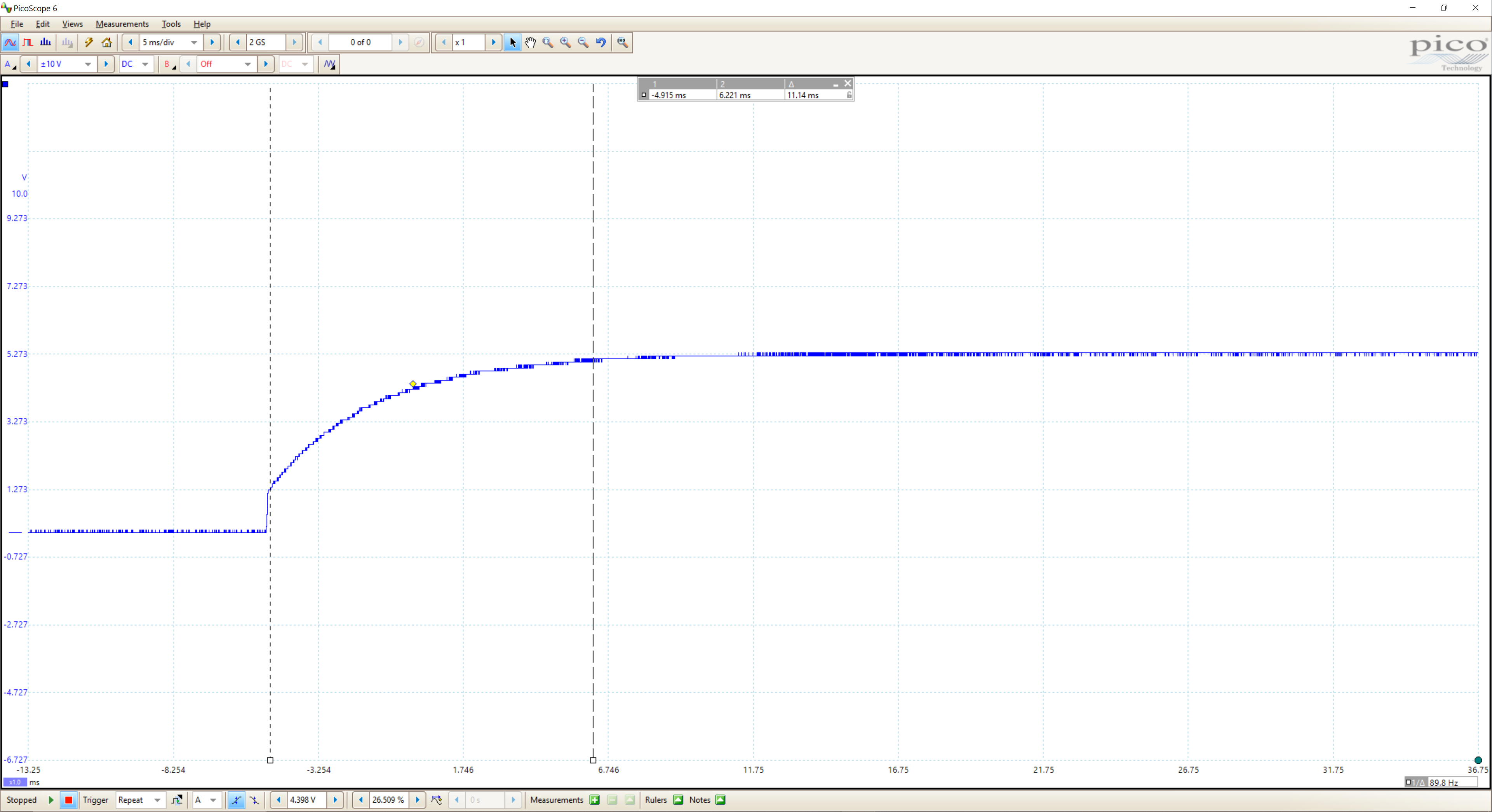
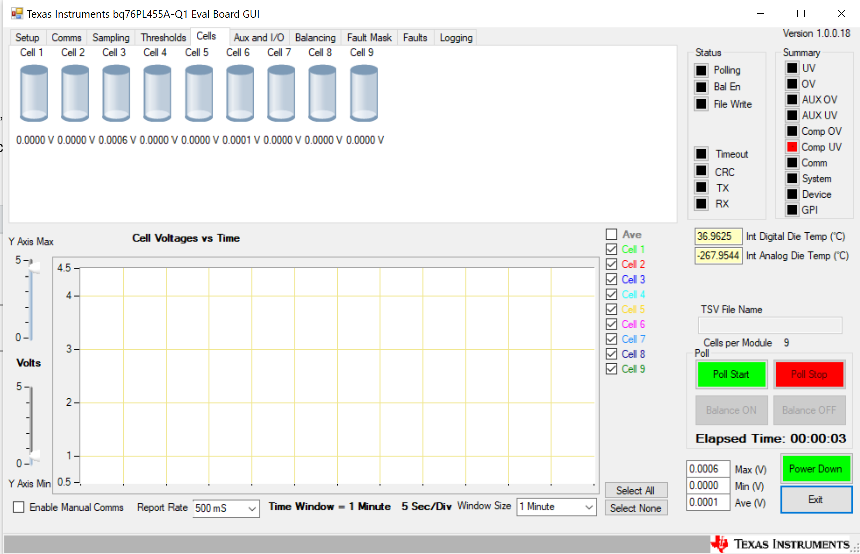
The issue is, we are not able to get any voltages from the cell measurements Vsense (batteries 9-16 is tied short). All cells measure basically couple mV of noise. We connected the chip to a USB converter, so its not the microcontrollers firmware, we see cells 1-9 being almost zero on the GUI. One hint that shows the Analog Front End has an issue is the analog die temperature is invalid -268C, I also do not get anything for REF2 AFE voltage. Everything else in the chip works, digital side and AUX ADC, also EQ lines (balancers) are working fine as well. 

Measurement on the Vsense lines from meter are as expected, from bottom of the stack, 3.5V, 7.0V, 10.5V etc... from Vsense1 to Vsense9 (above 9 is tied together). The BQ chip itself also has being changed out once to make sure its not a faulty hardware.

Register 14, NPNB controller is disabled on boot. The cells are plugged in, then the 3V3M is enabled, in that sequence. Is there a power sequence requirement here? Or some other requirement for the VP line? Any other possibilities for cells with no data? 

Thanks for any help!

  • Hi Billy,

    Can you please measure all of the voltage rails and especially plot VP over time to check if there are any oscillations?

    Thanks,

    Taylor
  • Hi Taylor,

    I upped the voltage on VP slightly, now at 5.35V, but doesn't seem to do much. Here's the plot of the voltage coming up:

    Took about 11mS to come up to voltage (I'm now using external 3V3 to turn on the regulator, the power supply takes 10mS to come up on enable).

    I also checked all other ones, using same probe.

    VDIG = VP through 1 ohm, confirmed

    VIO = 3V3 external

    VM = -5 internally generated okay.

    V5VAO = 5.3V internally generated.

    OUT1/OUT2, I probed this spot when its digitizing (GUI set to poll), and I see no voltage here.

    WAKEUP signal is set to high when the uC powers up, otherwise chip goes to sleep. 

    I also powered cycled the chip by toggling 3V3M on and off. Doesn't seem to help. Same issue.

    Attached screenshot of UI output:

  • Hi Billy,

    Can you send the full schematic?

    Thanks,

    Taylor
  • Sure thing, see attachment.BQ76.pdf

  • One thing interesting to note is that if the WAKE pin is not high, the chip goes to sleep immediately, all communication is off. Only if WAKE pin is toggled high that the chip will communicate. It looks like it was in some kind of shutdown mode, there was no power drawn before the WAKE pin is flagged high. Different behavior from the eval board, but doesn't seem to matter too much.

  • Is there a way to test whether or not the analog section of the chip is working?
    I'm getting VM = -5V, VREF2 is at 0 when set to digitize, it almost seems like the analog MUX is not working.

    Also, I just wired NPNB to the TPS1601A regulator enable line, while the cell voltages are still at zero, the Comp OV/UV seems to be working. I set the voltages of the comparator and it does flag faults when its outside of actual cell voltage range.

    Also, BAT0 and GND is connected on an external board.

  • Hi there,

    Just want to post to say the bug is resolved. We had a part library error where OUT2 pin is connected to ground rather than OUT1. Was very difficult to catch.

    Thanks,

  • Hi Billy,

    Thanks for following up, glad you were able to resolve this!

    Regards,

    Taylor