This thread has been locked.

If you have a related question, please click the "Ask a related question" button in the top right corner. The newly created question will be automatically linked to this question.

TPS92661-Q1: TPS92661-Q1 communication trouble

Part Number: TPS92661-Q1

Hello,

I am trying to use a tps 92661 on a LED adaptive headlight, and i am having some trouble in communicate between the TPS and the MCU (Arduino MEGA).

I am using a data logger and it was suppose that when i write a message the TPS should answer me, but nothing happens after sending the message.
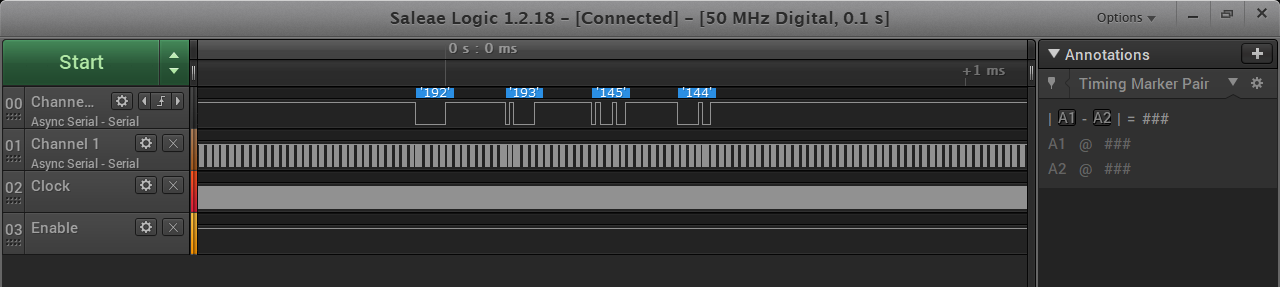
192 = 0xC0
193 = 0xC1
145 = 0x91
140 = 0x8C

Can anyone help me?

#define ENABLE_PIN 5 //PIN 4 DO TPS
#define CLOCKOUT 10 //PIN 8 DO TPS

void lmm_wr_1_reg(uint8_t lmm, uint8_t regaddr, uint8_t data);
void lmm_uart_xmit(uint8_t data);

const int prescale = 1;
const int ocr2aval = 3;

void setup() {
pinMode(ENABLE_PIN, OUTPUT);
digitalWrite(ENABLE_PIN, LOW);

pinMode(CLOCKOUT, OUTPUT);


TCCR2A = ((1 << WGM21) | (1 << COM2A0));

// Set Timer 2 No prescaling (i.e. prescale division = 1)
//
// CS22:0 = 001: Use CPU clock with no prescaling
// CS2 bits 2:0 are all in TCCR2B
TCCR2B = (1 << CS20);

// Make sure Compare-match register A interrupt for timer2 is disabled
TIMSK2 = 0;
// This value determines the output frequency
OCR2A = ocr2aval;

// put your setup code here, to run once:
Serial.begin(9600);
delay(100);
Serial1.begin(125000);
delay(100);

digitalWrite(ENABLE_PIN, HIGH);
delay(100);

while (Serial.available() == 0);
while (Serial.available() != 0)
Serial.read();
Serial.println("READ CLOCK SOURCE");

Serial.println(lmm_rd_1_reg(0x00, 0xc1));

while (Serial.available() == 0);
while (Serial.available() != 0)
Serial.read();
Serial.println("SET CLOCK SOURCE");

lmm_wr_1_reg(0x00, 0xc1, 0b00000011); // tps 0, SYSCFG SCMASTER 1 PWR1
//lmm_wr_1_reg(0x01, 0xc1, 0b00000001); // tps 1, SYSCFG SCMASTER 0 PWR1
while (Serial.available() == 0);
while (Serial.available() != 0)
Serial.read();
Serial.println("READ CLOCK SOURCE");
Serial.println(lmm_rd_1_reg(0x00, 0xc1));

while (Serial.available() == 0);
while (Serial.available() != 0)
Serial.read();
Serial.println("SET LEDS");
lmm_wr_1_reg(0x00, 0xB1, 0b00001000); //ENABLE DO LED 12 (12A9)
lmm_wr_1_reg(0x00, 0x0D, 0b00000000); //LED12
lmm_wr_1_reg(0x00, 0x2D, 0b11111111); //LED12

while(1);
}

King regards

Vasco Mendes

  • Hello Vasco,

    Can you take actual oscilloscope waveforms of TX, RX, and CLK at the TPS92661 pins.   I can't see what is going on in the transactions.  What address are you using?  A schematic would be useful to verify connections. 

    Have you used the TPS92661 EVM and GUI to help verify your code? 

    If you can't supply schematics publically then we can take this offline and communicate via email.  Just click on my name and then add me via "+Connect" button on the top right then send me your contact information and I will email you. 

    -Francis

  • Dear Francis,

    We are two finalists automotive engineering students, and our final graduation project consists in designing and build an adaptive Matrix headlight for motorcycles. Our ideia is to have one LED matrix controlled by two LED Drivers (TPS92662–Q1), and both controlled by one Arduino MEGA (via UART).

    First of all, we are using a TPS92662 with datasheet from TPS92661, so this is an right option?

    We don't use the TPS92661 EVM and GUI to help verify my code. It's possible get an example from code?

    How we have a TPS92662 and the datasheet isn't much detailed, we used the schematic from example at TPS92661 datasheet.

    TX and RX wave:


    Clock ave:


    King regards, 

    Vasco Mendes

  • Hello Vasco,
    Sorry for the delay in response.

    You are sending logic analyzer screen shots on not oscilloscope wave forms.

    The TPS92661 and the TPS92662 have a fair amount of differences and you can't interchange them. I can't post example code on this forum but I can send you some offline. Note, it isn't for Arduino and is for MSP family of micros. Also, what did you do with Address pins, those are inputs and shouldn't be left floating.
    -Francis Houde
  • Dear Francis,

    > Sorry for the delay in response. 

    Although we are in a hurry due to academic year deadlines any help is welcome and helpful.


    > You are sending logic analyzer screen shots on not oscilloscope wave forms. 

    For the reported problem , i.e. communications the logic analyzer is more suitable.


    > The TPS92661 and the TPS92662 have a fair amount of differences and you can't interchange them.

    After reading your post, we suspect that maybe the problems that we are having, may be related to the fact that we based our code and schematic on the TPS 92661 - Q1 datasheet.  We've searched for the TPS 92662 - Q1 datasheet and only found a very simple one without logical or electrical specifications: http://www.ti.com/lit/ds/symlink/tps92662-q1.pdf

    If you have a better one, can you send us,  or point us were to find it?

    > I can't post example code on this forum but I can send you some offline. Note, it isn't for Arduino and is for MSP family of micros.

    Thanks, we will adapt the code for arduino framework ourselves.

    >Also, what did you do with Address pins, those are inputs and shouldn't be left floating.

    Regarding the address pins, we connected all of them to the ground in order to have the following  address of the device: 0x00; 


    Here is my e-mail if you want to send us some files (like the datasheet and code examples):

    e-mail: 2151719@my.ipleiria.pt

    once again, thank you very much


    kind Regards,

    Vasco Mendes