Hello there,
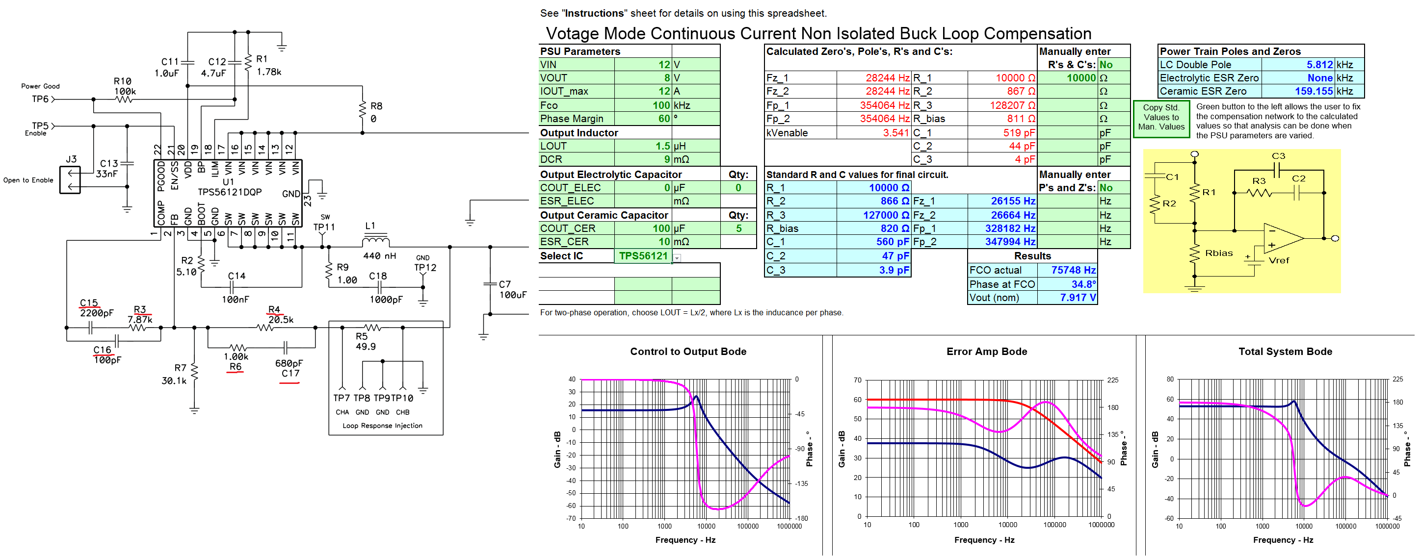
I am looking for an IC and it's circuit (schematic) able to convert 12V DC (battery input) to constant 8V DC. The output current range is around 10 to 15A. This PCB and its IC will run a bunch of servos.
Thanks for your help,
Hello there,
I am looking for an IC and it's circuit (schematic) able to convert 12V DC (battery input) to constant 8V DC. The output current range is around 10 to 15A. This PCB and its IC will run a bunch of servos.
Thanks for your help,