This thread has been locked.

If you have a related question, please click the "Ask a related question" button in the top right corner. The newly created question will be automatically linked to this question.

UC3710: Using UCx710 ICs to drive high side FETs

Part Number: UC3710
Other Parts Discussed in Thread: UCC27531,

Hi,

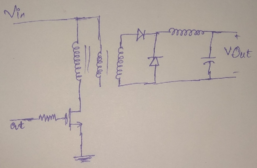
The datasheet for the UCx710 gate drivers mention it to be a low side driver. If I were to use it to drive a high side FET, say for example mosfet in a buck converter, what would be the easiest way to achieve it? A normal solution would be to use a AC coupled transformer to drive the FET. However, the DIP and SOIC packages for the IC have separated power and logic grounds. Does this mean that I can bootstrap the output circuit and use it directly to drive the FET.

Thanks

Nandha

  • Hi Nandha,

    Thanks for your interest in our driver, my name is Mamadou Diallo, I will help address your questions.

    UCx710 is one of our older low-side driver, depending on specific features of interest, I can maybe suggest our latest and most optimized drivers with better switching performance and characteristics.

    I have copied below few devices that you might find equally (or better) suitable for your application.

      UC3710 UCC27511A UCC27524 UCC27519 UCC27517
    Order now Order now Order now Order now Order now
    Datasheet Datasheet Datasheet Datasheet Datasheet
    SubFamily Low-side drivers Low-side drivers Low-side drivers Low-side drivers Low-side drivers
    Number of channels (# ) 1 1 2 1 1
    Peak output current (A ) 6 8 5 4 4
    Input VCC (Min ) (V ) 4.7 4.5 4.5 4.5 4.5
    Input VCC (Max ) (V ) 18 18 18 18 18
    Rise time (ns ) 25 9 7 8 9
    Fall time (ns ) 20 7 6 7 7
    Input threshold CMOS CMOS CMOS CMOS CMOS
    TTL TTL TTL
    Prop delay (ns ) 35 13 13 17 13
    Features N/A Split Output Enable Pin Enable Pin Hysteretic Logic
    Rating Catalog Catalog Catalog Catalog Catalog
    Operating temperature range (C ) 0 to 70 -40 to 140 -40 to 140 -40 to 140 -40 to 140
    Package Group PDIP | 8 SOT-23 | 6 MSOP-PowerPAD | 8 SOT-23 | 5 SOT-23 | 5
    SOIC | 16 PDIP | 8
    TO-220 | 5 SOIC | 8
      SON | 8

    As for driving a high-side FET using a low-side driver, you may achieve this with a combination of an isolated bias, small transformer and level shifter as shown below: This would accommodate any high duty cycles needs while providing constant bias to the high-side FET. In the attached example, I am using a paralled dual-channel driver but it is certainly applicable to a single channel driver as well. This image is from a tech note

    http://www.tij.co.jp/jp/lit/an/snvt010a/snvt010a.pdf

    A second method to achieve this is shown on figure 3 of the app note below using UCC27531:

    http://www.ti.com/lit/an/slua669a/slua669a.pdf

    Please let us know if you have further questions or press the green button if this addressed your questions.

    Regards,

    -Mamadou

  • Hi Mamadou,

    Thanks for the comprehensive reply. Wanted to confirm whether I would be able to use UCx710 devices in place of UCC27531 in the same configuration as in the application note you had mentioned at the end of your reply. I am stuck with UCx710 devices as I need space grade drivers for my application.

    Thanks

    Nandha

  • Hi Nandha,

    Though we have not tested it nor simulated this topology with this device, using UCx710 may also work in that implementation.

    Please let us know if you have additional applications questions or press the green button if this answered your questions.

    Thanks.

    Regards,

    -Mamadou

  • Hi,
    I have other queries regarding the usage of UCx710 ICs. The highlights of the datasheet mention 3ns delays and 20ns rise and fall 2.2nf, 8ns rise and fall to 30nF (a bit confusing as it has faster response to a larger load). These numbers are not verifiable with the electrical characteristics tables. Please look into the issue and advise.
    Thanks
    Nandha
  • Hi Nandha,

    Thanks for pointing that out.

    Please refer to the EC table on page 3 of the datasheet.

    Please let us know if you further questions.

    Regards,

    -Mamadou
  • Hi Mamadou,
    I am interfacing the input of the 3710 directly with a function generator. The IC functionality checks out but I see a really long turn off time, around 300ns along with a distorted gate waveform. Could you provide working waveforms of this IC on a different setup. this would conform that the issue is something with the setup or the PCB and not the IC.
    Thanks
    Nandha
  • Hi Nandha,

    Can you please verify how many ICs you tested? I ask because we have not had any returns/issues associated with this device?
    Also can you confirm value of your gate resistance? Are you using a single turn-on and turn-off path between driver output stage and gate? I am also assuming that the FET(s) is(are) placed as closed as possible to the driver to minimize stray inductance at the gate.

    Please feel free to share schematic/layout and I will gladly review.

    Regards,

    -Mamadou
  • Hi Nandha,

    I have not heard from you, I will assume that you've resolved the issue and mark this thread as "closed". If that's the case, feel free to share how you resolved the problem for other e2e users to learn from.

    If you're still having issues, please let us know by further posting on this thread with the additional information requested in my previous response.

    Regards,

    -Mamadou
  • Hi Mamadou,

    Your previous answer had resolved my query regarding the IC. My later queries were for testing of this IC in a specific setup. Felt it was not relevant to post on this thread. The issue I faced is as follows

    To test transformers designed for forward and flyback converters, I designed a crude PCB with just the power elements and the FET driven by UC3710(TO package). The INV and NINV pins are connected to a function generator.  

    Due to a slow turn off, there was high switching losses, in the order of 8-10W. There was an improvement in performance when I provided a low resistance path for turn off using a diode between the gate and OUT pin of UC3710. Moreover, the input signal was given using a twisted pair cable with long leads. The issue was mostly due to the setup and not the IC. Didn't find such issue when I used an alternate setup to just switch on and off the FET

  • Hi Nandha,

    Thanks for the follow up.

    Our drivers as well as typical gate drivers work best with very little stray inductance in the circuit reason why building prototypes using long wires to connect components are usually not the best way to evaluate circuit performance. The inductance will significantly degrade the efficiency of the design from the switching losses occurring.

    Please let us know if you have further gate drivers needs.

    Regards,

    -Mamadou